

Anti-Drone Steel Structure
High-tensile, anti-kinetic steel canopies and geometric grids engineered to protect critical energy and strategic assets from aerial and drone-based threats.
What Anti-Drone Steel Structure Projects Demand From the Steel
The problems clients bring us most often on this kind of project, and how the steel package answers each one.
Protecting critical assets from aerial threats
Canopies, grids and mesh structures are engineered as a physical barrier over the protected area, with the structural system chosen from the span and the required opening pattern.
Openings that admit air and light but stop intrusion
Mesh apertures and grid geometry are specified with the operator, balancing visibility, ventilation and the size of the object to be stopped.
Impact and wind loads on an open structure
Members and connections are checked for wind, ice and the design impact case your engineer specifies, with redundancy in the grid.
Fast deployment over existing installations
Modular grids are fabricated for bolted erection around live equipment, with foundations and supports planned to avoid shutdowns.
How Your Project Is Built
Three phases from the first drawing to handover. Move over a phase to see what happens in it and what you receive at the end of it.
Engineering & Foundation
The structure is sized in a 3D BIM model before any steel is cut. While members are fabricated in the factory, earthworks and independent foundations are poured on site in parallel from the anchor bolt templates we ship first.
- 3D BIM model before any steel is cut
- Anchor bolt templates shipped first
- Foundations poured in parallel with fabrication
Fabrication & Erection
Columns, beams and trusses are CNC-cut, welded, tested and trial-assembled in the yard, then shipped in erection sequence. On site the frame is bolted from marked members with the erection drawings and our remote or on-site guidance.
- CNC-cut, welded, tested and trial-assembled
- Shipped in erection sequence
- Bolted on site from marked members
Envelope & Handover
Cladding, insulation, openings and rainwater goods close the building; dimensional and coating records are handed over with the as-built drawings and the certificate package.
- Cladding, insulation, openings and rainwater goods
- As-built drawings with dimensional and coating records
- Certificate package at handover
Certifications & Compliance
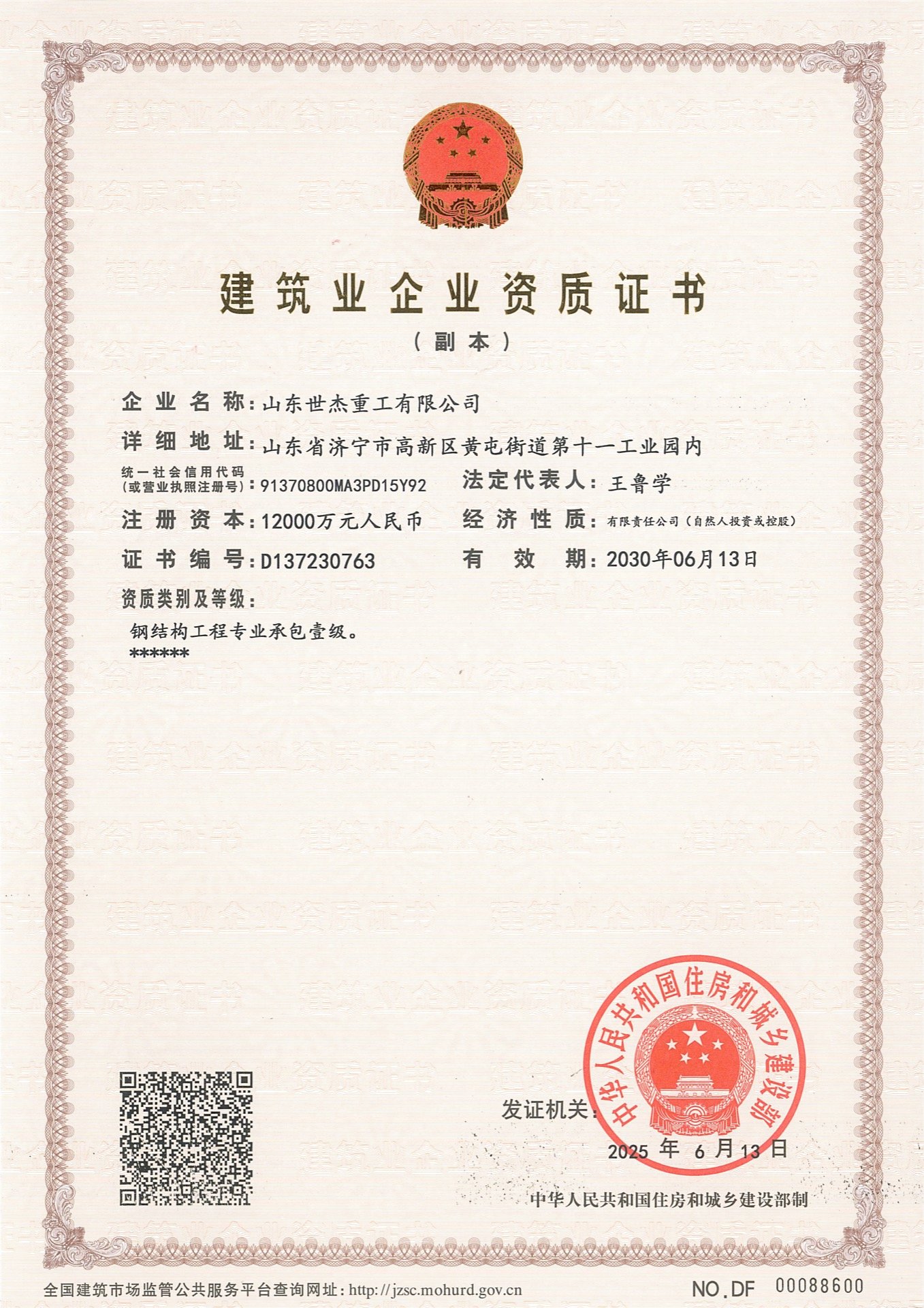
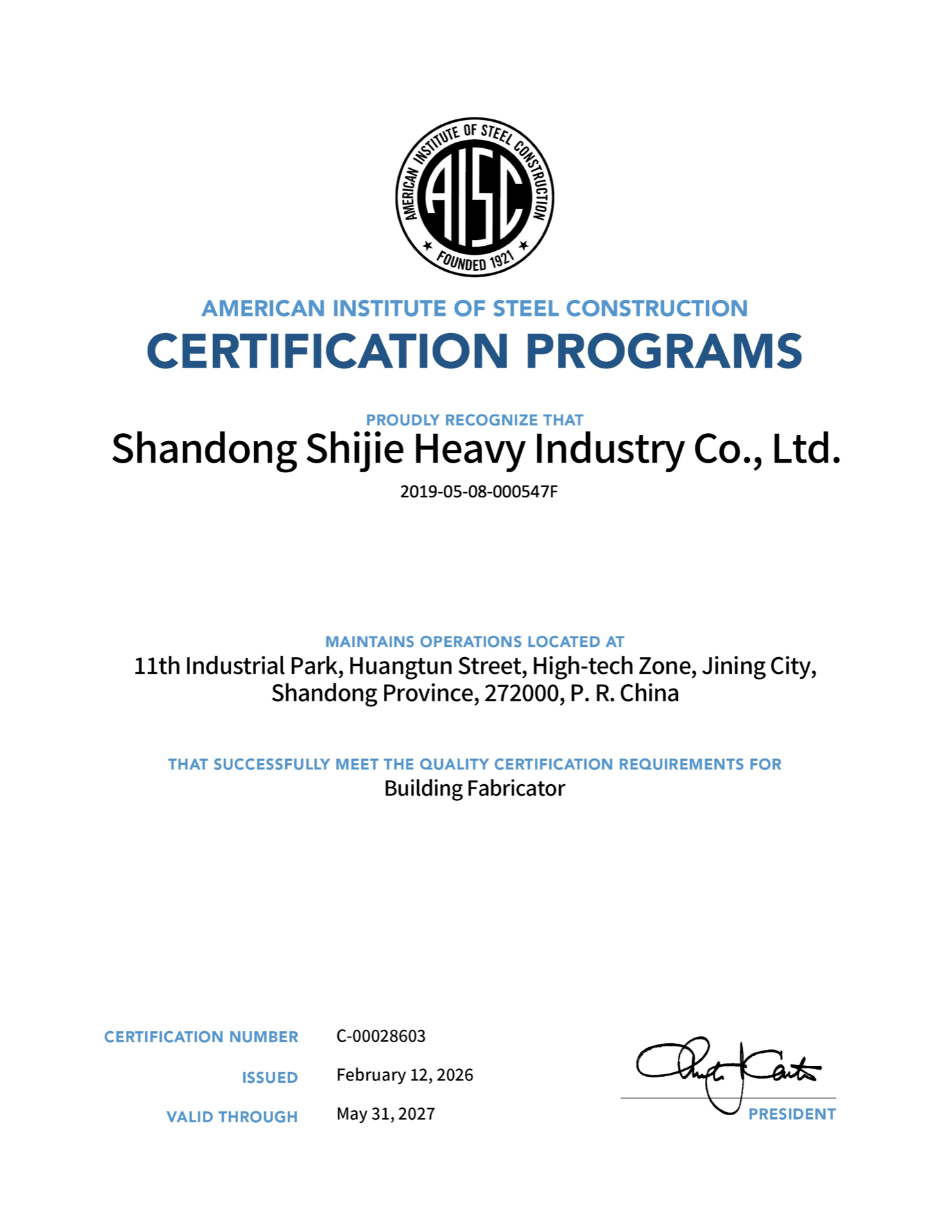
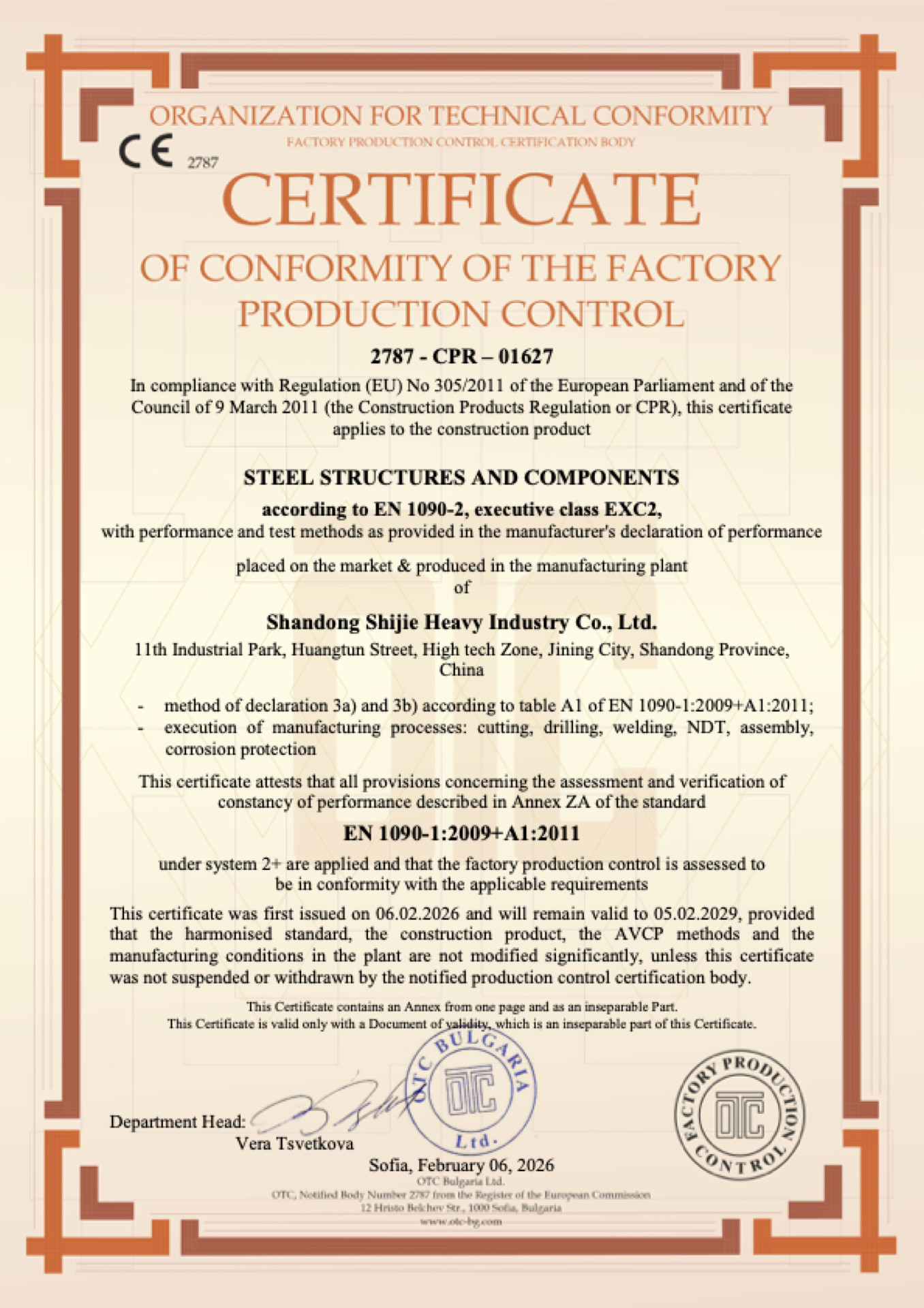
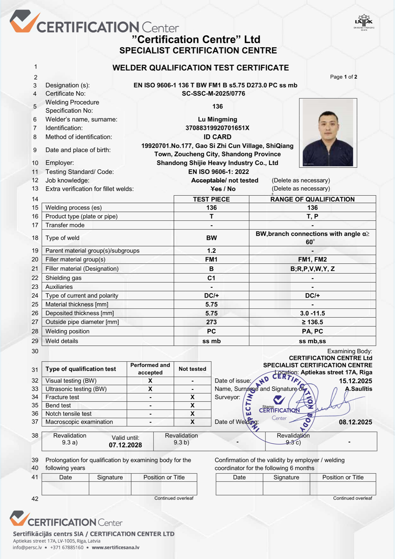
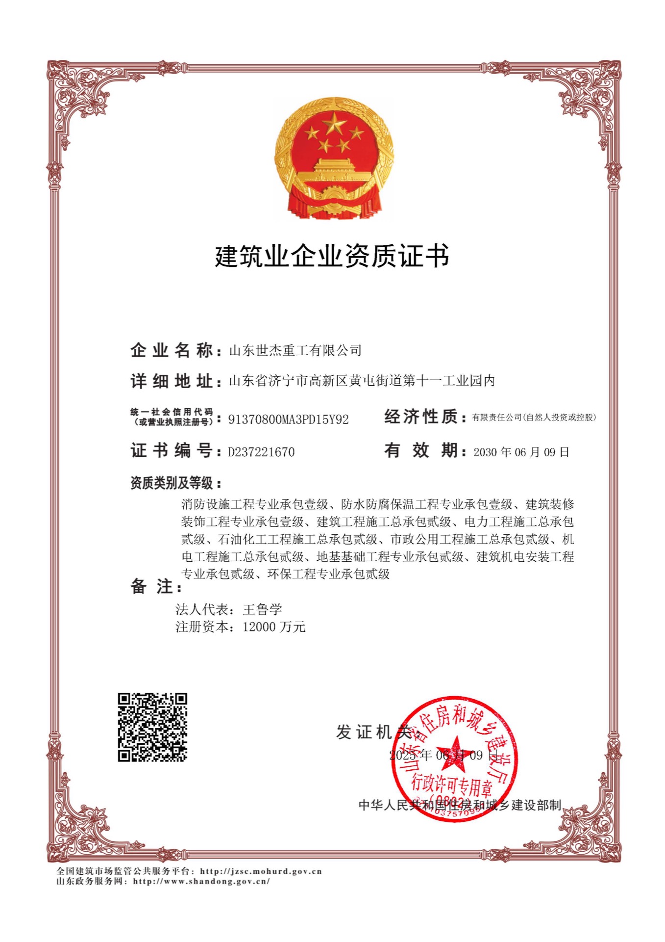
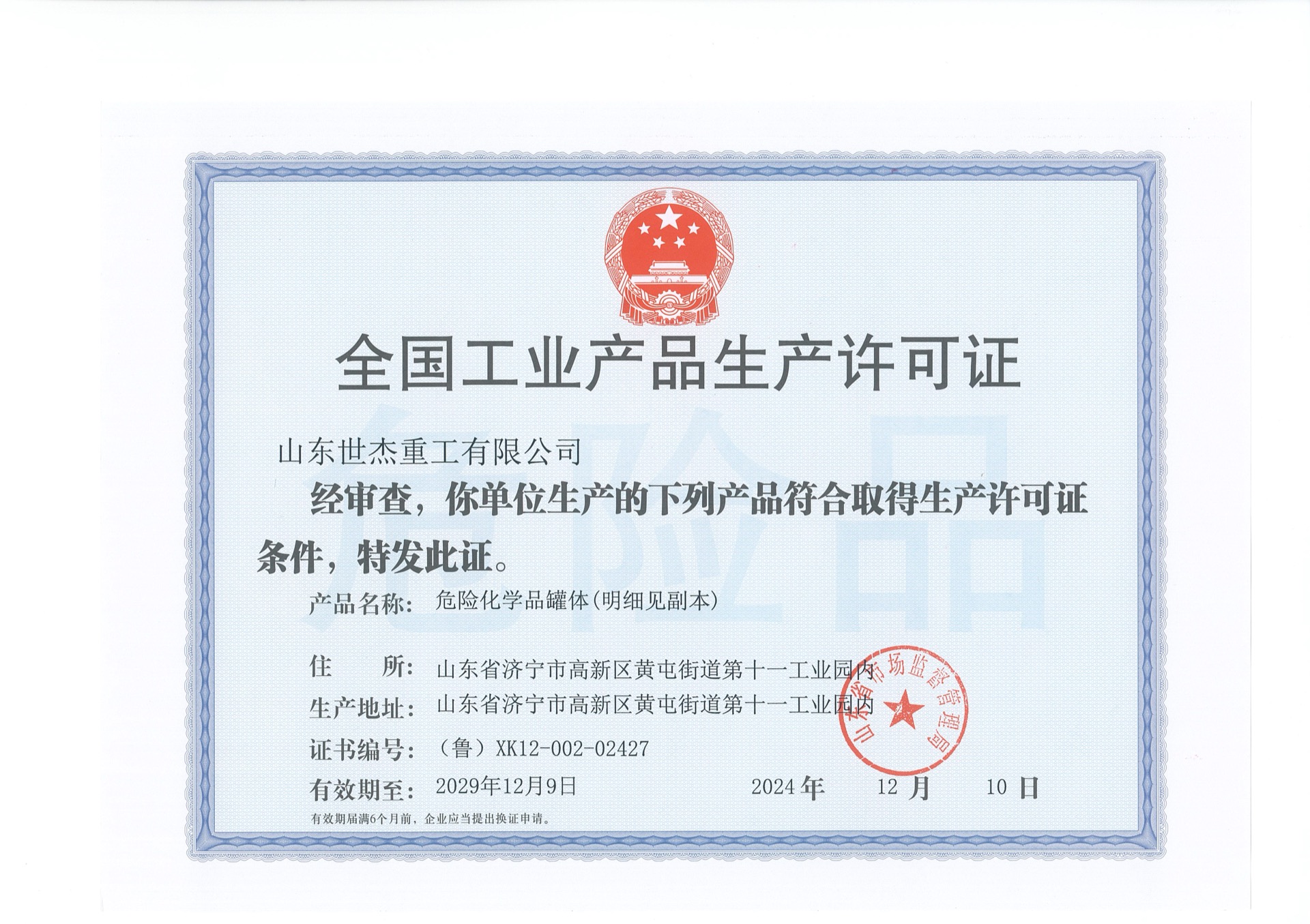
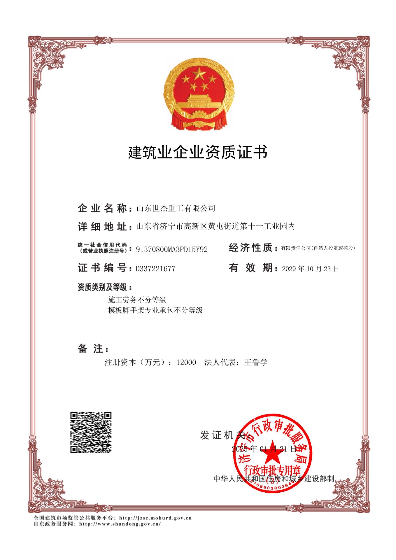
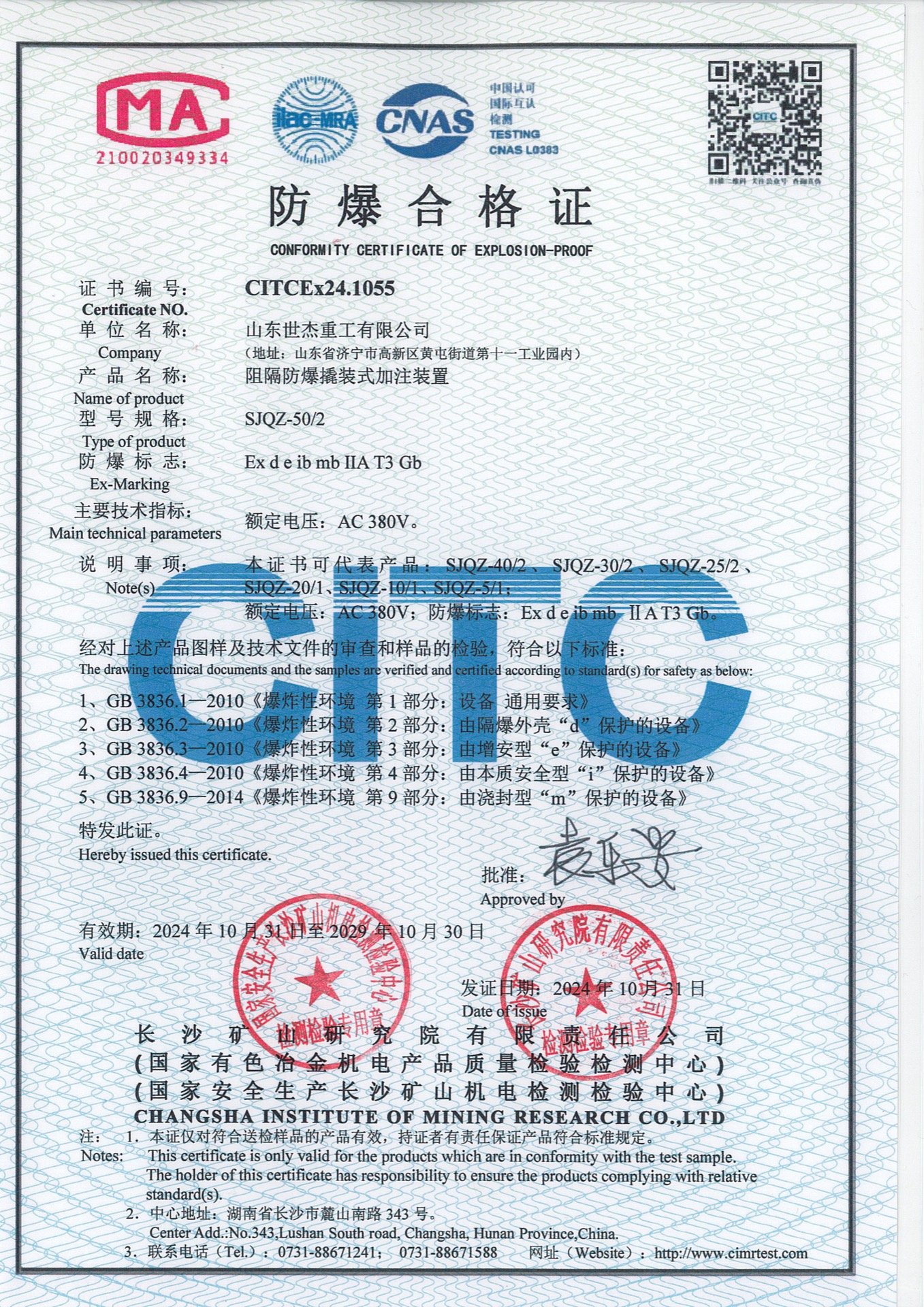
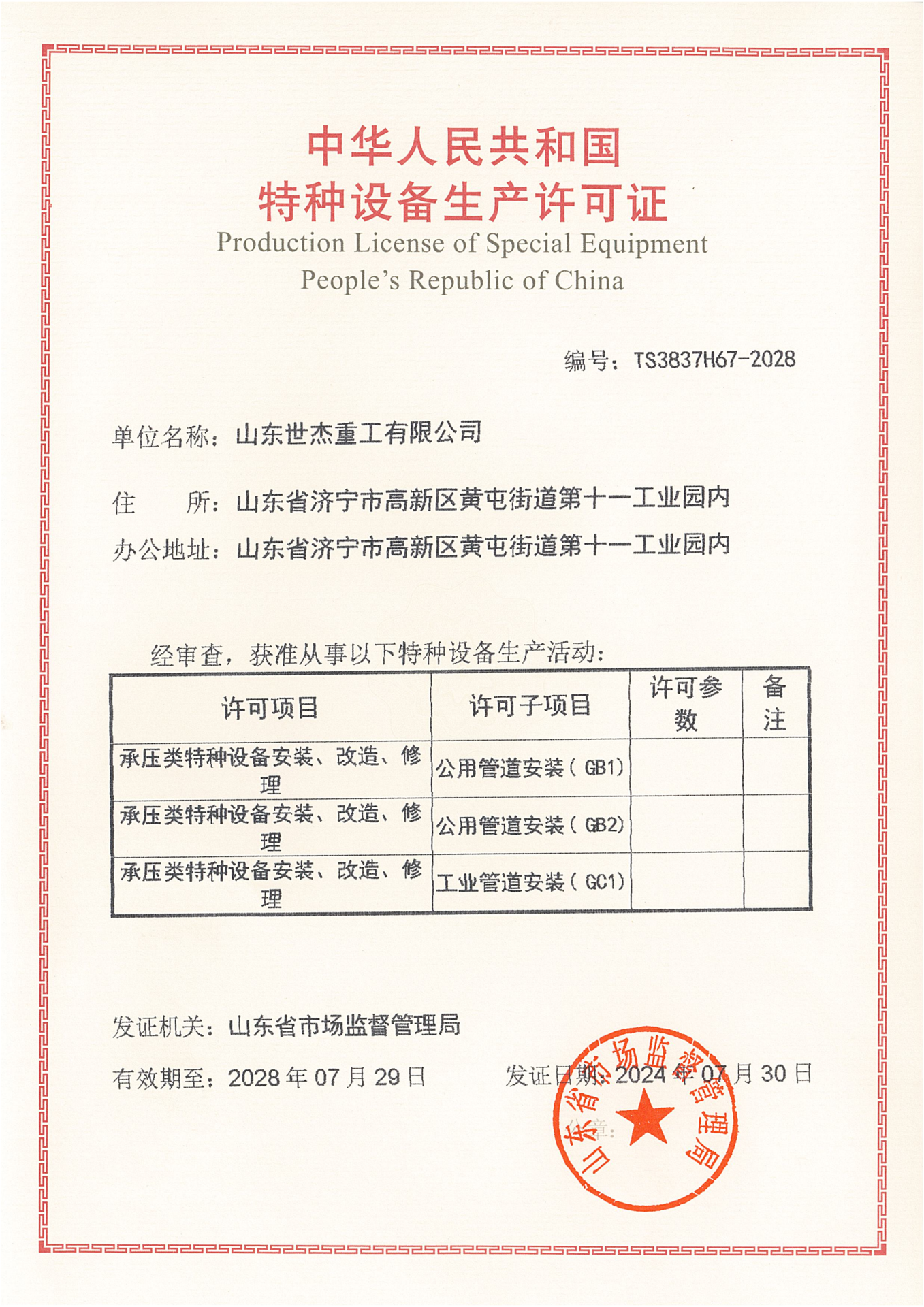
Every shipment leaves with the documents an auditor asks for. Scroll the row and open any certificate at full size.
Technical Parameters
Typical parameters of the Space Frame Structures used for this application. Final values are fixed at detailing from your drawings and local loads.
| Parameter | What it is set from |
|---|---|
| Design basis | AISC 360 / EN 1993-1-1, as the project specifies |
| Execution class | EN 1090-2 EXC2 (certificate 2787-CPR-01627) |
| Nodes | Bolted spherical nodes and welded hollow spheres machined to the node schedule; hole angles and thread sizes follow the drawings |
| Struts | Circular hollow sections to EN 10219 / ASTM A500, cut to length with cones and sealing plates welded on |
| Welding | AWS D1.1 / EN ISO 9606 qualified procedures and welders |
| NDT | 100% UT or MT on critical full-penetration welds; welded spheres inspected before dispatch |
| Trial assembly | 1:1 physical trial assembly in the yard to AISC / EN 1090-2 practice: bolt hole groups checked for at least 95% free entry, span, camber and node coordinates held within ±2.0 mm, with a dimensional report and photographs before coating. |
| Marking | Every node and strut stencilled and barcoded with its grid reference, matching the packing list and 3D erection drawings |
| Corrosion protection | ISO 12944, system selected per site environment (C3–CX) |
| Documentation | MTRs, forging certificates, WPS/PQR, NDT and DFT reports with every shipment |
Recommended Product Systems
The structural systems we fabricate most often for this kind of project. Each opens the product page with sub-systems, parameters and FAQ.
Space frame structures for clear-span roofs: bolted-ball and welded-sphere space frames for stadium, terminal, station, gas station and toll plaza canopies, made as a matched kit of nodes, struts and supports.
Steel truss structures for long-span roofs: circular pipe trusses, square tube trusses, angle steel trusses and H- or I-beam trusses fabricated as roof truss systems for terminals, stations, industrial halls and exhibition centres.
Building envelope systems quoted with the steel frame: roof and wall cladding, insulation and waterproofing, industrial doors, windows, louvers and ventilators, gutters and downspouts.
Related Projects
Steel structures we fabricated and shipped for the same kind of building.
Frequently Asked Questions
Can you supply space frame components only, for a roof we weld locally?
Yes. Bolt spheres, welded spheres, cones, sleeves, set screws and high-strength bolts are quoted as components against your node schedule; pipe struts can be supplied cut to length or sourced locally.
What is the difference between a space frame roof and a steel truss roof in your quotation?
A space frame is a three-dimensional grid of struts and nodes; a truss roof is planar or tubular trusses at bay spacing with purlins between them. Span, roof shape and architectural intent decide it; we quote either from the roof plan and loads.
Do you supply the supports and bearings for a space frame roof?
Yes. Support bearings, brackets and the high-strength bolts are quoted with the node kit — see the Space Frame Members & Supports sub-system — so the roof lands on supports drilled to the same template.
Which design code do you fabricate to?
Whichever your design specifies. We work to AISC 360 or Eurocode 3 (EN 1993) for design intent, and execute to EN 1090-2 EXC2 under certificate 2787-CPR-01627. State the code in your enquiry and the quotation is issued against it.
Can you issue calculations our building authority will accept?
Yes. We provide English structural calculation reports with load combinations and 3D models. Where local regulations require a licensed local engineer to stamp the drawings, we supply the calculation package for their review.
What is a realistic lead time?
For a typical single-building scope the standard cycle is 40 to 50 days: 1–2 weeks from contract to 3D models and shop drawings for your approval, then 4–5 weeks for procurement, CNC fabrication, welding, coating and loading. Drawing approval is the part you control.
Do you supply the enclosure as well as the frame?
Yes. Roof and wall cladding, insulation, waterproofing, doors, windows, ventilation and drainage are quoted as one package — see Enclosure & Cladding Systems . Single-source supply removes the interface risk between frame and envelope.
How do we verify your certificates?
Ask us for the certificate together with its Document of validity — they are issued as an inseparable pair. We send both with the welding annex on request. Details are published on our certificates page .
Send Us Your Drawings or BOQ
Tell us the footprint, span, crane capacity and local loads — our engineering team reviews every request and replies with a preliminary assessment.
- Reviewed by our engineering team
- AISC certified · CE marked EN 1090-2 (EXC2)
- Mutual NDA available on request
🔒 100% Private and Secure, No Spam