

Portal Frame Structure

Large-Span, Cost-Effective Solutions for Industrial & Storage Spaces

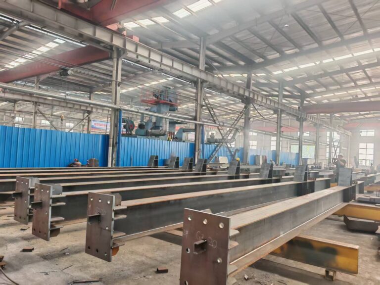
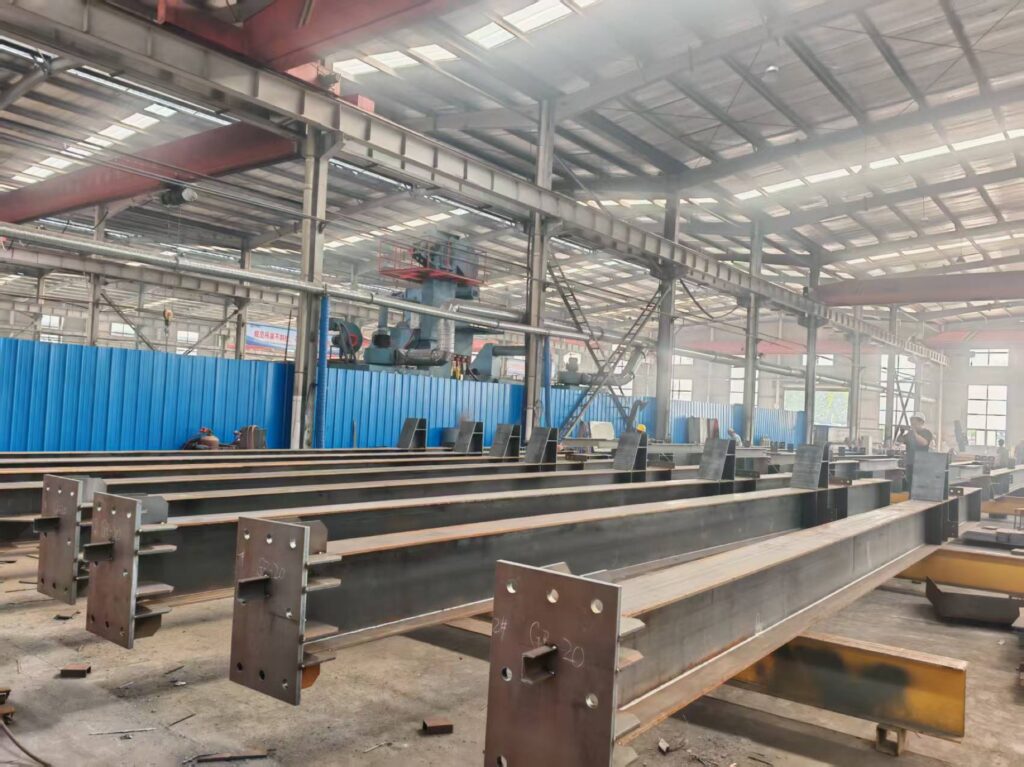
The Portal Frame is the most mature and efficient light steel structure system in global industrial construction today. Utilizing high-strength H-section columns and tapered beams as the main load-bearing skeleton, combined with cold-formed thin-walled steel (C/Z purlins), steel portal frame achieves an internal column-free clear span of up to 40–50 meters with extremely low dead weight. Whether for manufacturing workshops requiring frequent heavy material lifting or logistics centers maximizing cubic space, prefab metal buildings cuts construction time in half while ensuring ultimate wind/seismic safety.

The High-ROI Engine for Global Industrial & Storage Spaces

Accelerated Monetization — 100% factory prefabrication and all-bolted on-site dry assembly bypass adverse weather delays, ensuring your facility is operational 3–6 months ahead of competitors.

Boundless Space & Maximum Efficiency — Eliminating internal columns grants absolute freedom for forklift routes, AGV robots, and fully automated assembly line layouts.

Seamless Heavy Crane Integration — H-section columns are factory-pre-welded with heavy-duty corbels to safely support 5t to 50t overhead cranes, meeting extreme lifting demands in heavy manufacturing.

Present the optimal solution to your Board of Directors: input your workshop dimensions and crane capacity now to receive a customized 3D conceptual design and BOM cost estimate within 48 hours.

COMPONENTS

Components of the Portal Frame System

01

Primary Framing

H-Section Columns · Box / Rectangular Columns · Cruciform Columns · Circular Columns …

02

Secondary Framing

Z-Section Purlins · C-Section Purlins · Rectangular Purlins · High-Frequency Welded H-Purlins …

03

Bracing System

Round Steel Bracing · Angle Steel Bracing · Pipe Bracing · Square Tube Bracing …

04

Connection & Fasteners

Tie Rods · Sleeves (32mm / 1-1.5m) · Anchor Bolts

Technical Specifications

ItemSpecification
Clear Span40 – 50 m standard, up to 100 m+ on request
Design CodesAISC 360 / Eurocode 3 (EN 1993) / GB 50017
Steel GradesQ355B/C/D, ASTM A572 Gr.50, S355JR/J2
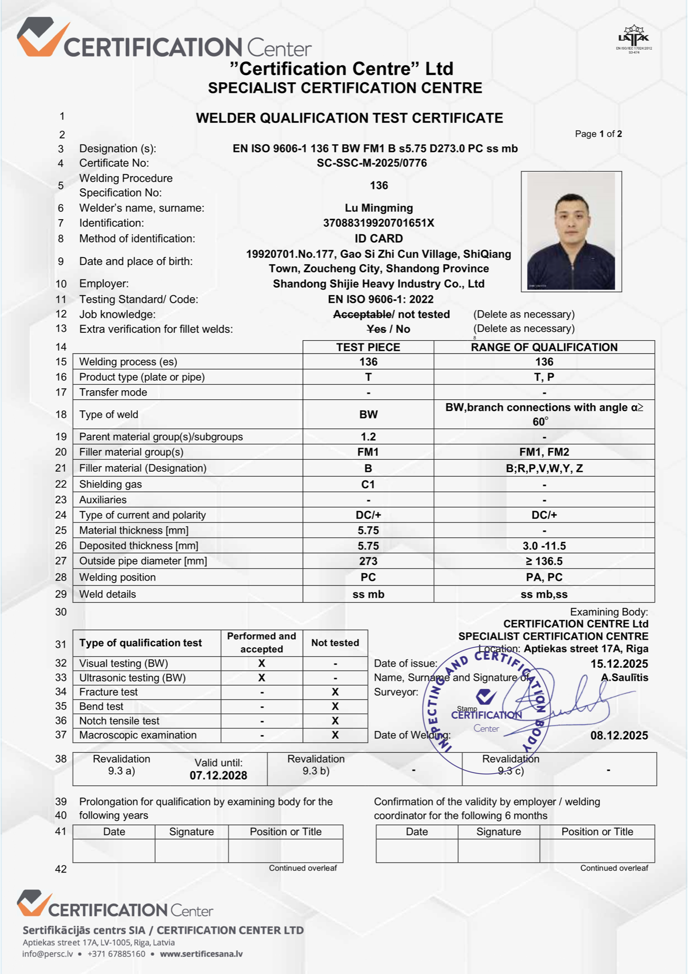
Welding StandardAWS D1.1 / EN ISO 9606, ISO 5817 Quality Level B
Crane Capacity5 t – 50 t overhead cranes (pre-welded corbels)
Wind ResistanceCustomisable up to 250 km/h peak gust
Surface PreparationSa 2.5 (ISO 8501-1) shot blasting, 45–75 µm profile
Coating SystemEpoxy zinc-rich primer + MIO intermediate + PU/fluorocarbon topcoat, ISO 12944 C3–CX
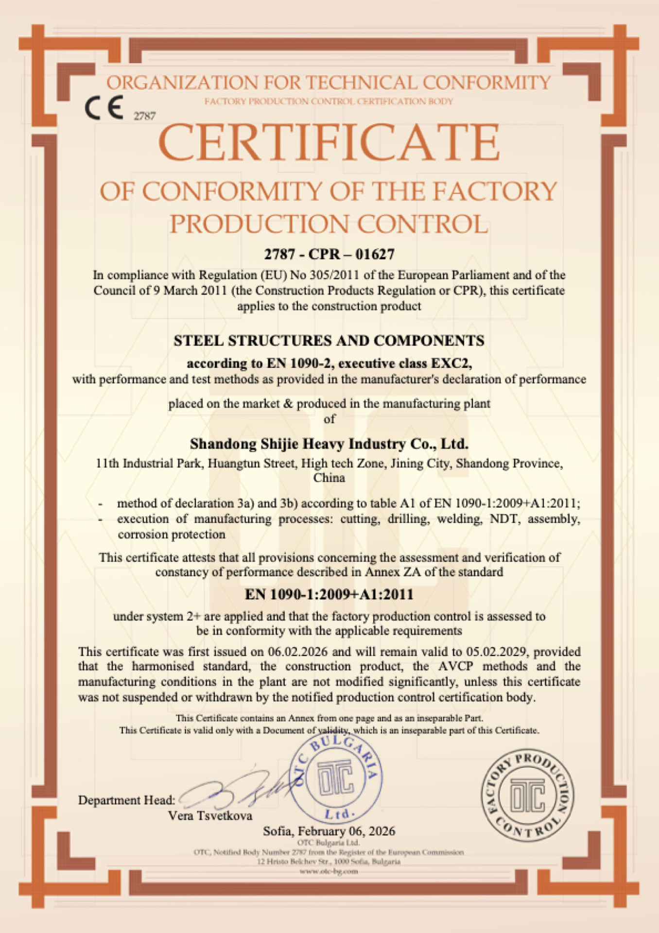
Execution ClassEN 1090-2 EXC2 (cert. 2787-CPR-01627), AISC COSP
Lead Time40 – 50 days for a 10,000 m² heavy workshop

Advantages vs Engineering Considerations

AdvantagesEngineering Considerations
Maximized Clear SpansDelivers ultra-large column-free clear spans (up to 100m+), providing 100% usable internal space for logistics warehousing, production lines and aircraft hangars.Best suited to single-storey and low-rise buildings; multi-storey floors or heavy mezzanines call for a braced or moment frame instead.
Material & Cost EfficiencyUtilizes tapered H-beams to distribute steel precisely where stress is highest, significantly reducing material redundancy and foundation civil works cost.Column-free spans increase rafter depth and foundation reactions; very long spans may be more economical as trusses or space frames.
Rapid Bolted Assembly100% factory pre-engineered with all-bolted on-site connections. Zero hot welding ensures rapid erection and drastically lower labour cost.Frames are sized to the stated crane duty and loads; a later change of crane class or roof equipment needs a design check.
Design Flexibility & ExpansionHighly modular node design allows straightforward future expansion simply by adding longitudinal bays without disrupting existing operations.Cold-formed purlins and girts reach their design capacity only with correct cladding fixing and bracing.
CERTIFICATIONS & COMPLIANCE

Certifications & Compliance

Every shipment leaves with the documents an auditor asks for. Scroll the row and open any certificate at full size.

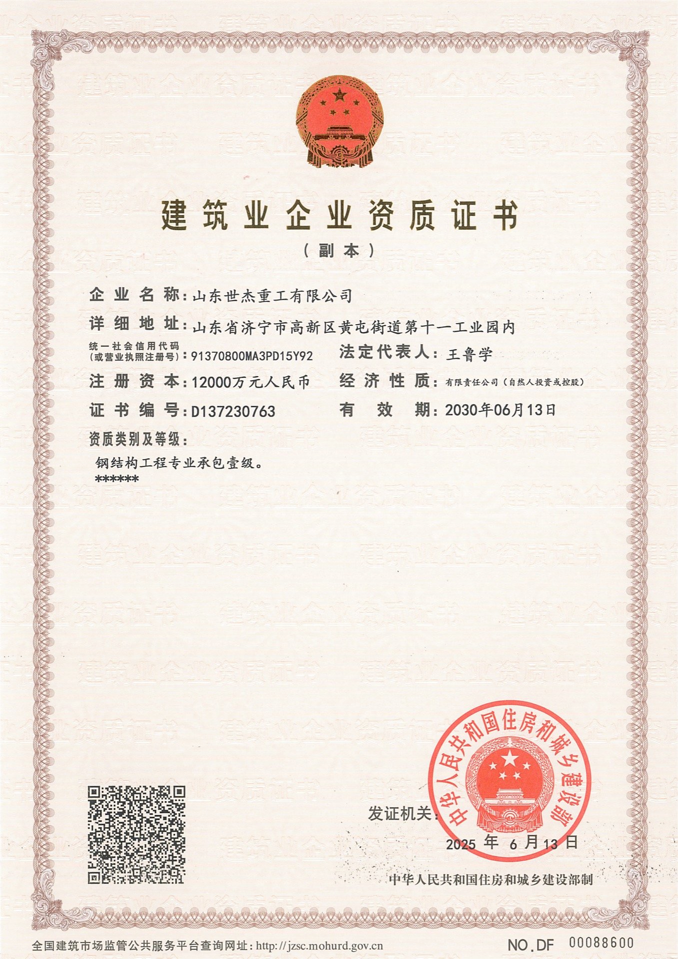
China Steel Structure Manufacturing Grade I

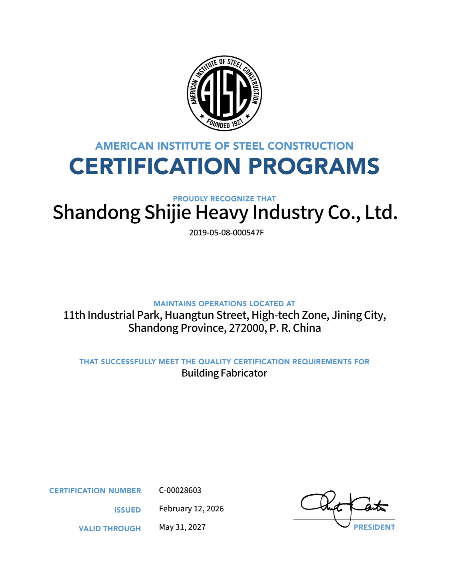
AISC Certification

CE Marking – EN 1090-2 (CPR 01627)

OTC Document of Validity

International Welder Certification

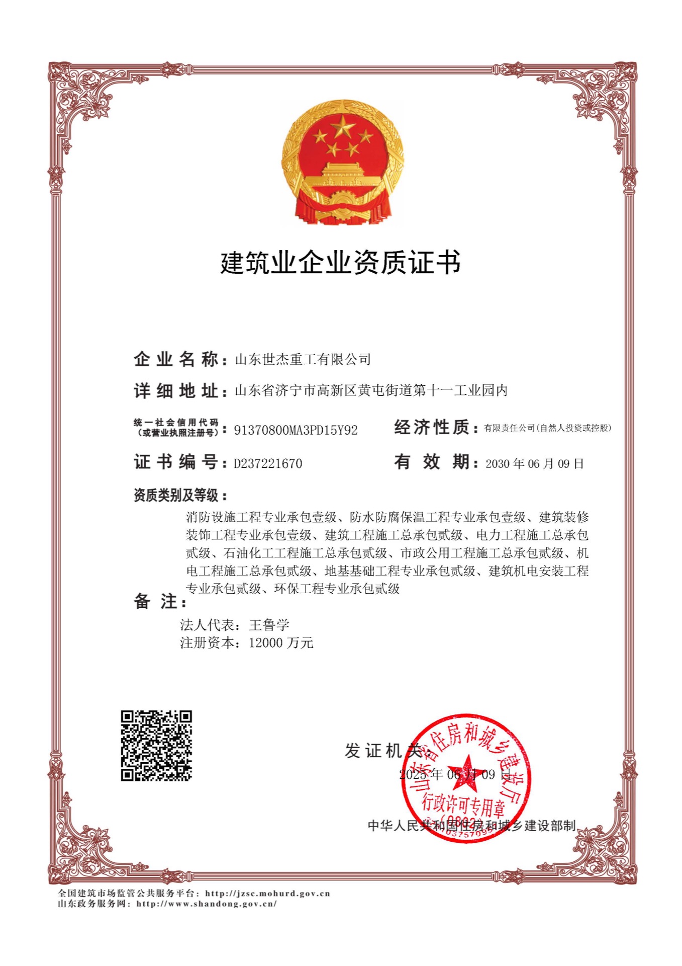
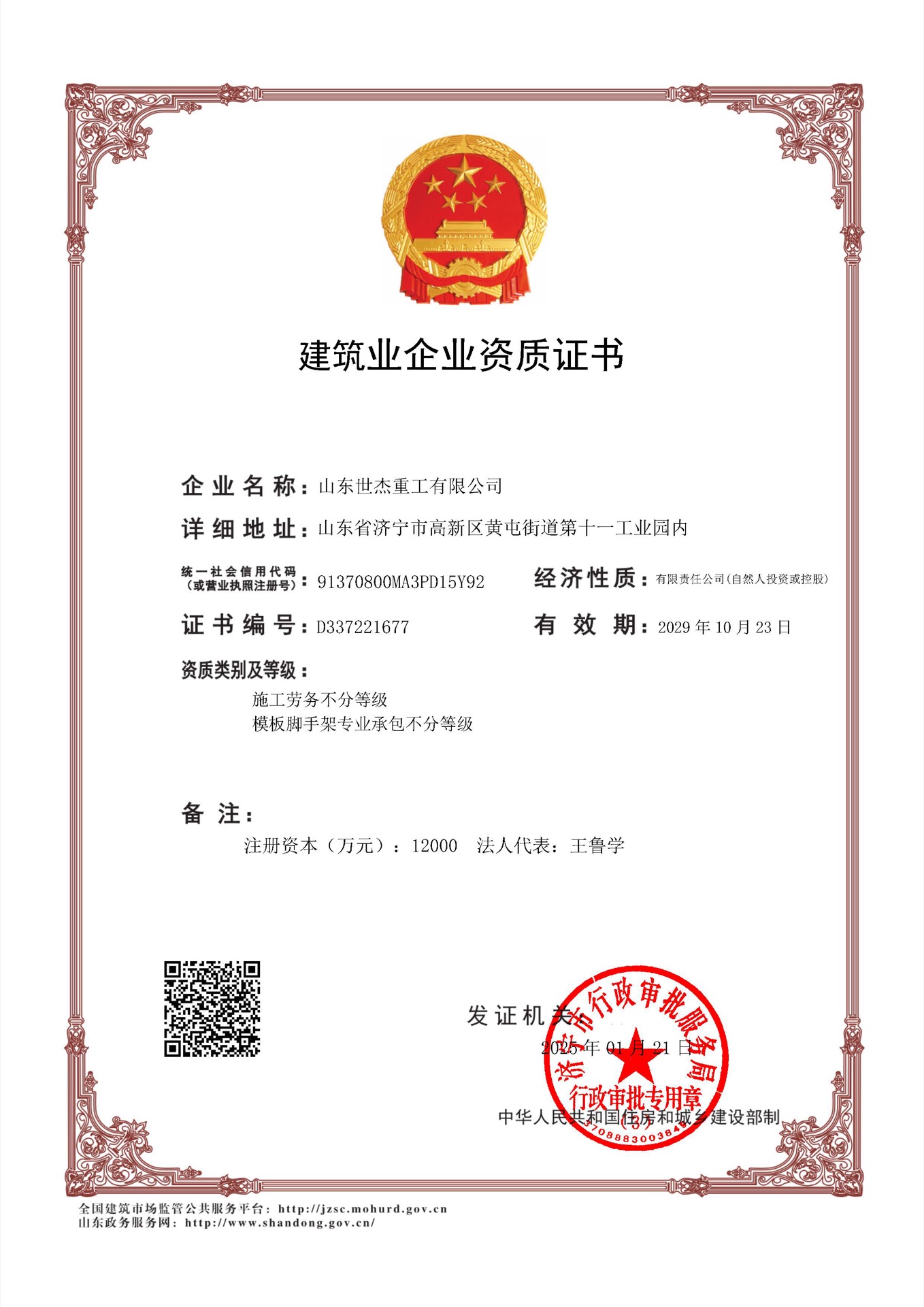
Enterprise Qualifications Portfolio

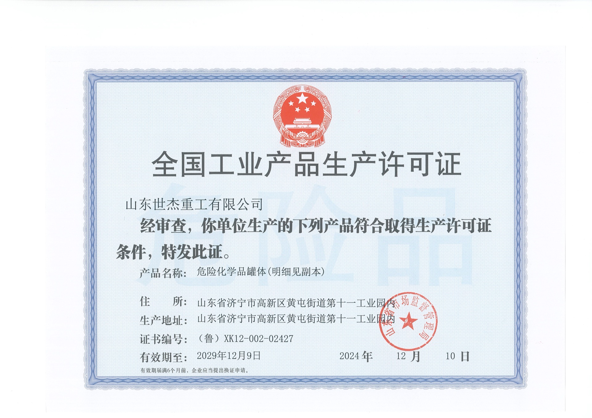
DG Packaging Certificate

Labor & Scaffolding Contracting

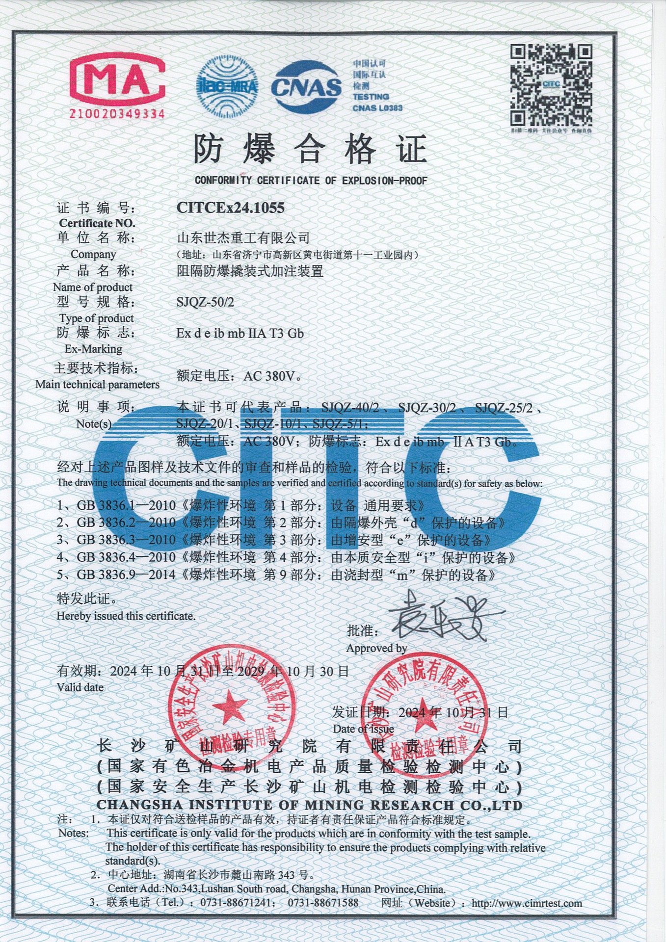
Explosion-Proof Certificate

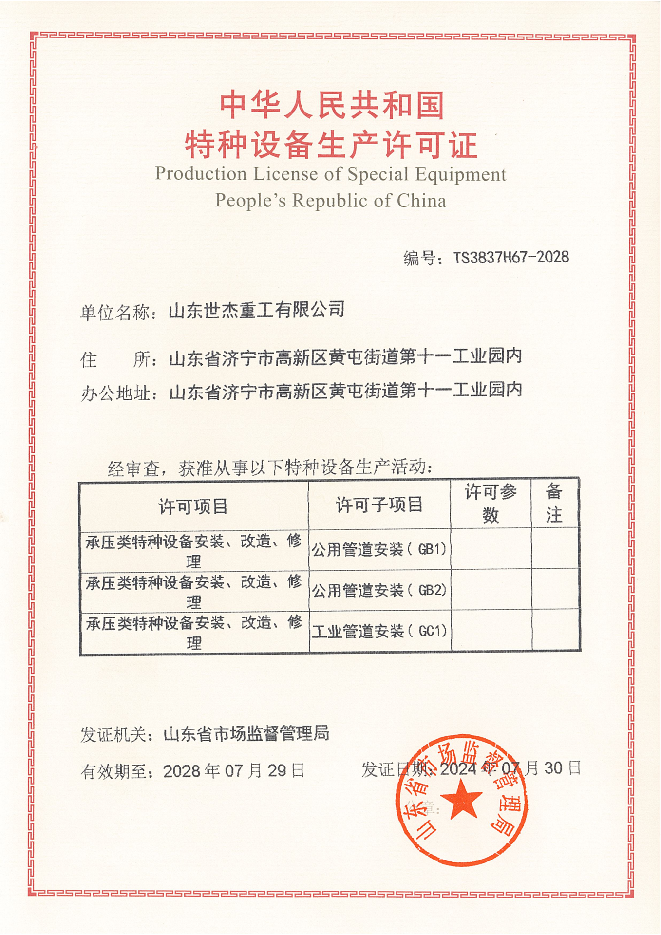
Industrial Pipeline Installation GC1

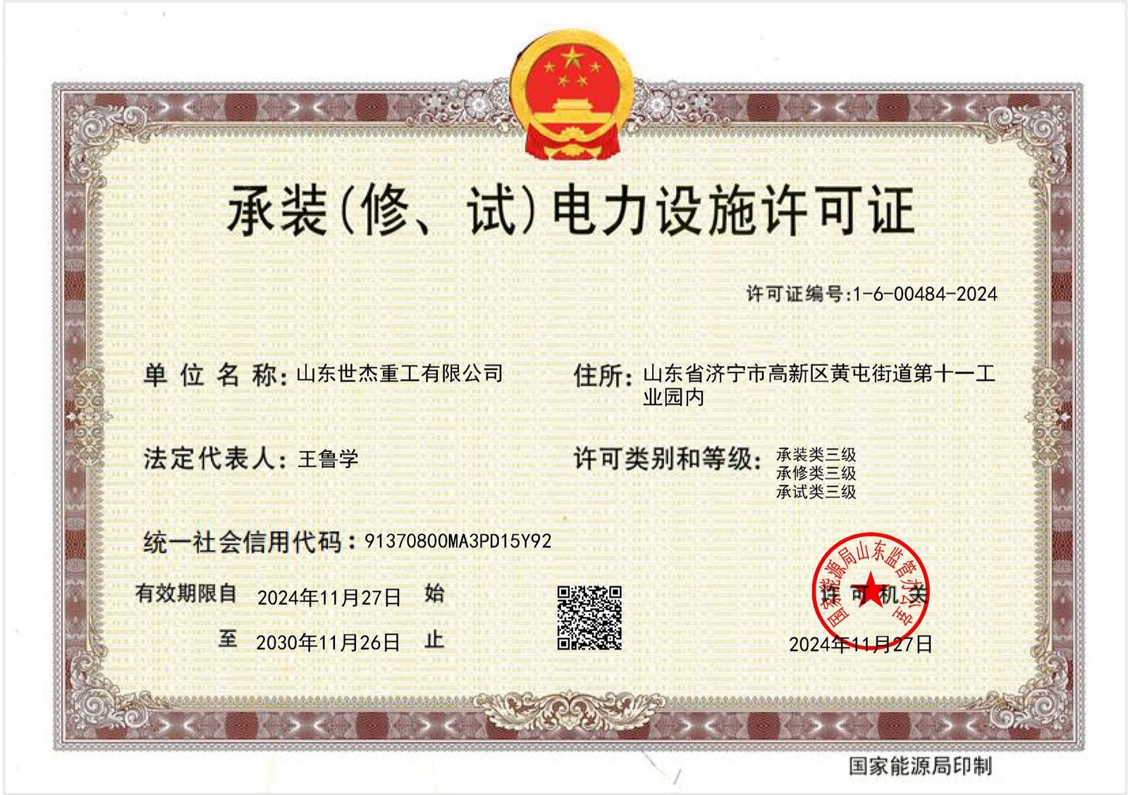
Power Facility License

Have drawings or a BOQ ready? Send them through the form and our engineers reply with a preliminary assessment.

SynJect

SynJect. Scale. Precision. Certainty.

SYNJECT delivers comprehensive steel structure solutions engineered for the global value chain. From investors seeking ROI to engineers demanding exact compliance, we transform complex blueprints into robust realities—on time and without friction.

SynJect ENGINEERING

From Microns to Megastructures — 12 Rigorous Stages Certified to AISC & EN 1090
Detailed Engineering & Shop Drawing DevelopmentNesting & Material OptimizationRaw Material Incoming InspectionCNC Cutting & Edge PreparationPrimary Structural WeldingWeld Distortion StraighteningNon-Destructive Testing (NDT)Trial Assembly & Shop AlignmentSurface Preparation & Protective CoatingFinal Quality Inspection & CertificationExport Packaging & Logistics ProtectionGlobal Field Erection & Site Management
Stage.01

Detailed Engineering & Shop Drawing Development

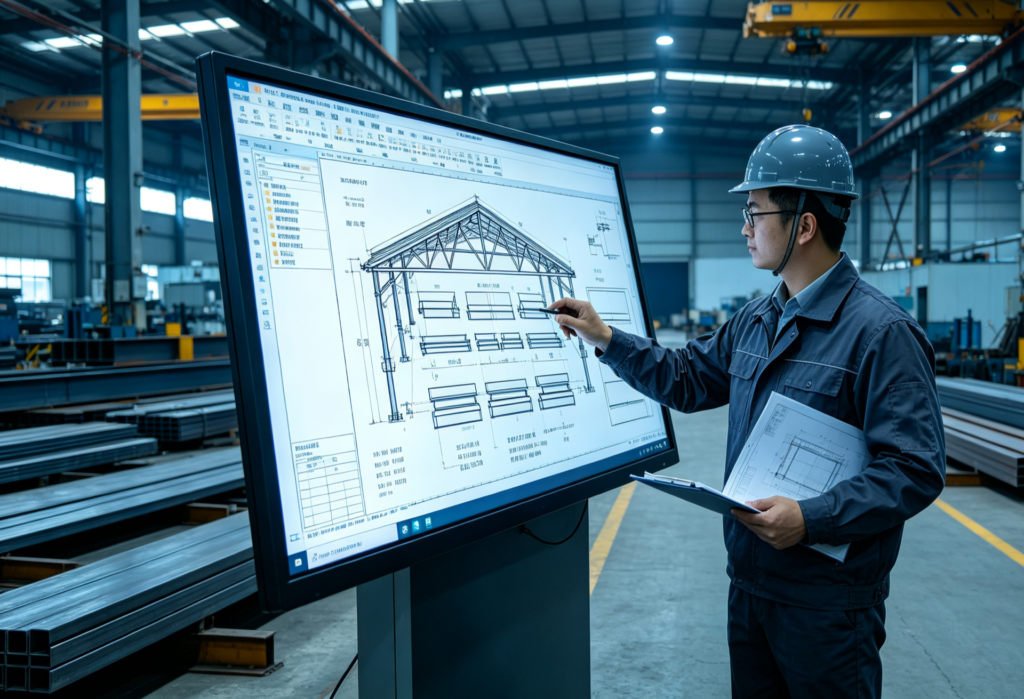
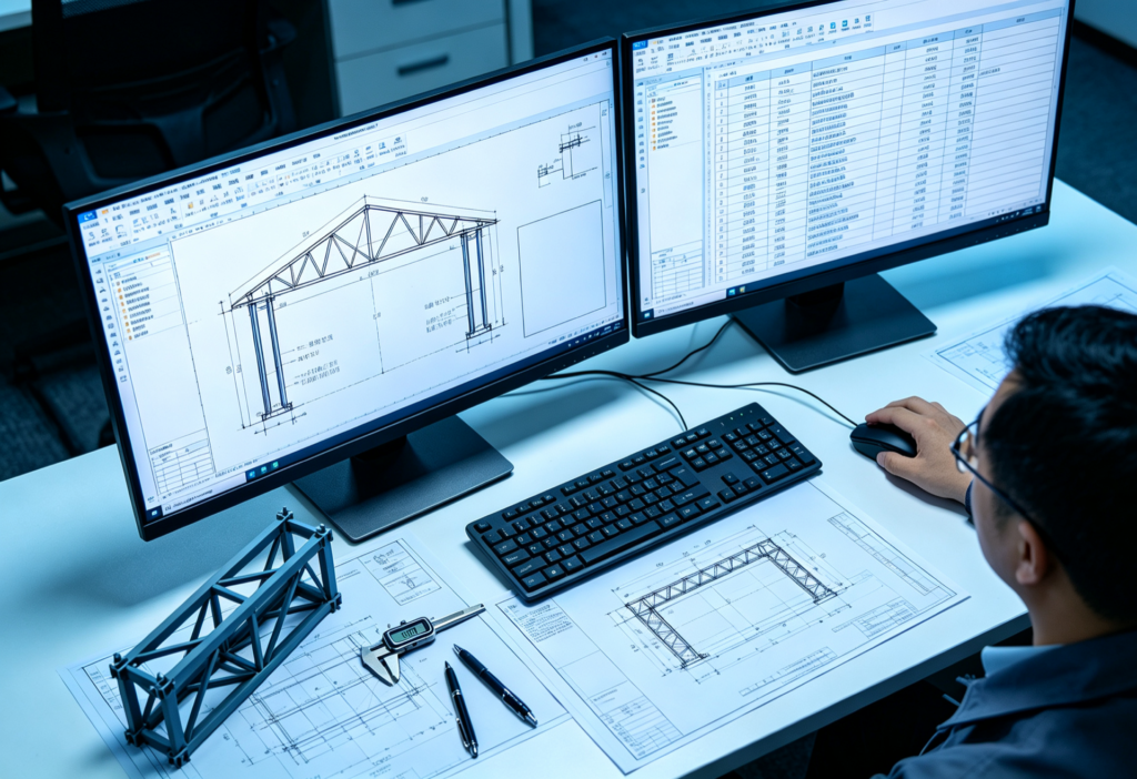
Utilizing advanced BIM platforms such as Tekla Structures, detailed 3D modeling and shop drawings are executed strictly in compliance with AISC 360 or Eurocode 3 (EN 1993). Connection designs are rigorously verified, with manufacturing drawings generated to ISO 2768-m tolerance standards. 100% clash detection with primary architectural and MEP systems is performed to ensure zero structural conflicts during field erection.

STANDARDAISC 360 / EN 1993
METRIC VALUETolerance ISO 2768-m
Stage.02

Nesting & Material Optimization

Intelligent nesting layouts are performed using advanced software like FastCAM/SigmaNEST in accordance with EN 10029 / ASTM A6 dimensional standards. Accounting for cutting kerf (2mm-5mm depending on plate thickness) and thermal contraction allowances, raw material utilization exceeds 92%. Offcuts are digitally barcode-tracked to ensure 100% mill test report (MTR) traceability.

STANDARDEN 10029 / ASTM A6
METRIC VALUEUtilization ≥92%
Stage.03

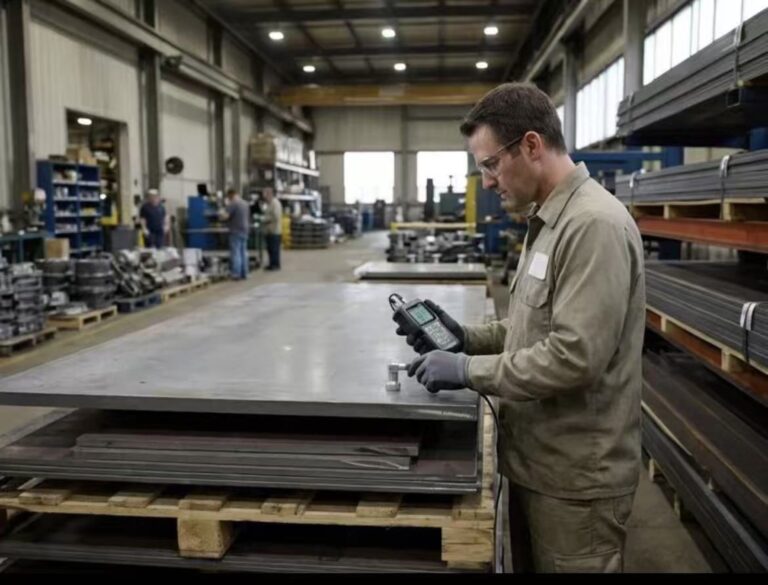
Raw Material Incoming Inspection

All structural steel (Q355B/C/D, ASTM A572 Gr.50, S355JR/J2) must be accompanied by EN 10204 3.1 Mill Test Reports (MTR). Incoming quality control conducts 100% dimensional and visual inspections under ASTM A6 / EN 10029, verifying thickness tolerances (Class A/B) and internal lamination integrity via Ultrasonic Testing (UT) to ASTM A435. Chemical composition and mechanical properties are spot-verified by accredited 3rd-party labs.

STANDARDEN 10204 3.1 / ASTM A435
METRIC VALUE100% MTR + UT
Stage.04

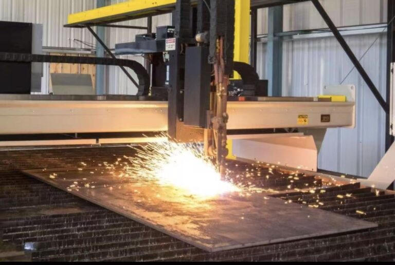
CNC Cutting & Edge Preparation

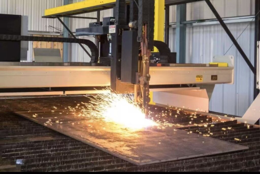
Plate profiling and component cutting are executed via CNC oxy-fuel, high-definition plasma, and multi-kW fiber laser equipment. Cut surface quality strictly complies with EN ISO 9013 for perpendicularity and surface roughness (Range 3/4 tolerance). Multi-axis CNC beveling machines execute weld prep bevel angles within ±2.5° and root face dimensions within ±1.0 mm.

STANDARDEN ISO 9013
METRIC VALUERa ≤12.5μm / ±2.5°
Stage.05

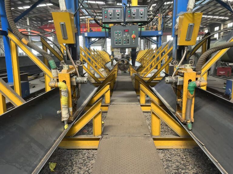
Primary Structural Welding

Welding is performed exclusively by AWS D1.1 or EN ISO 9606 certified welders using qualified Welding Procedure Specifications (WPS) supported by Procedure Qualification Records (PQR) per AWS D1.1 / ISO 15614. Submerged Arc Welding (SAW) and Flux-Cored Arc Welding (FCAW) dominate Complete Joint Penetration (CJP) and fillet welds. Heat input is strictly controlled, achieving weld quality levels conforming to ISO 5817 Quality Level B or AWS D1.1 standards.

STANDARDAWS D1.1 / EN ISO 9606
METRIC VALUEISO 5817 Level B
Stage.06

Weld Distortion Straightening

Post-weld angular distortion, camber, and sweep are rectified using automated hydraulic flange straighteners and controlled thermal flame straightening. Heating temperatures for High-Strength Low-Alloy (HSLA) steels are strictly maintained between 600-650 Celsius (air-cooled, zero water quenching) to prevent microstructural degradation. Post-straightening straightness tolerances meet ±3 mm, conforming to EN 1090-2 Execution Class 2 (EXC2) and AISC COSP standards.

STANDARDEN 1090-2 EXC2 / AISC COSP
METRIC VALUE≤ ±3 mm
Stage.07

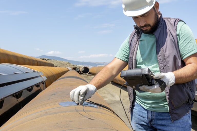
Non-Destructive Testing (NDT)

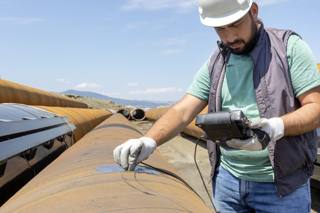
NDT protocols are operated by ISO 9712 / ASNT Level II certified NDT personnel. 100% of critical Complete Joint Penetration (CJP) welds undergo Ultrasonic Testing (UT per ISO 17640 / ASTM E164) or Magnetic Particle Testing (MT per ISO 17638 / ASTM E709). Radiographic Testing (RT) is applied as requested for heavy sections. Weld acceptance conforms strictly to ISO 11666 Acceptance Level 1 or AWS D1.1 criteria.

STANDARDISO 11666 Level 1 / AWS D1.1
METRIC VALUE100% UT on CJP
Stage.08

Trial Assembly & Shop Alignment

Complex geometries, long-span trusses, and heavy framing undergo 1:1 physical trial assembly or high-precision 3D laser scanning virtual assembly per EN 1090-2 / AISC requirements. Bolt hole alignment is verified (≥95% free-pass rate for high-strength bolts), and critical dimensions (span, camber, 3D spatial alignment) are verified within tight tolerance limits (±2.0 mm) to eliminate site fitting risks.

STANDARDAISC / EN 1090-2
METRIC VALUE±2.0 mm / ≥95% pass
Stage.09

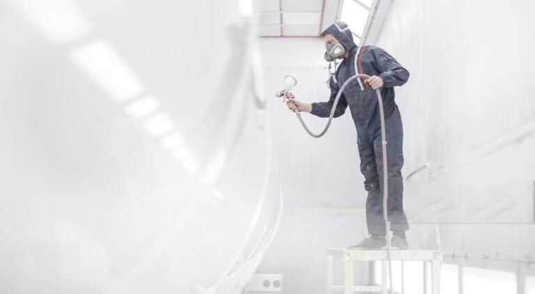
Surface Preparation & Protective Coating

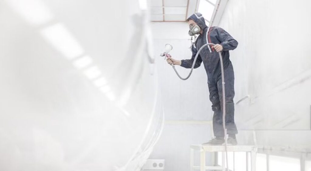
Structural members undergo automated shot blasting to achieve SSPC-SP10 / NACE No. 2 / ISO 8501-1 Sa 2.5 cleanliness, with a surface profile (anchor depth) of 45-75 microns. High-performance protective coatings are applied using airless spray technology in compliance with ISO 12944 (C3 to CX corrosive environments), featuring Zinc-Rich Epoxy Primers, Epoxy Micaceous Iron Oxide Intermediate coats, and Polyurethane/Fluorocarbon Topcoats. Dry Film Thickness (DFT) is verified adhering strictly to the 90/10 rule.

STANDARDISO 8501-1 Sa 2.5 / ISO 12944
METRIC VALUE45-75 μm profile
Stage.10

Final Quality Inspection & Certification

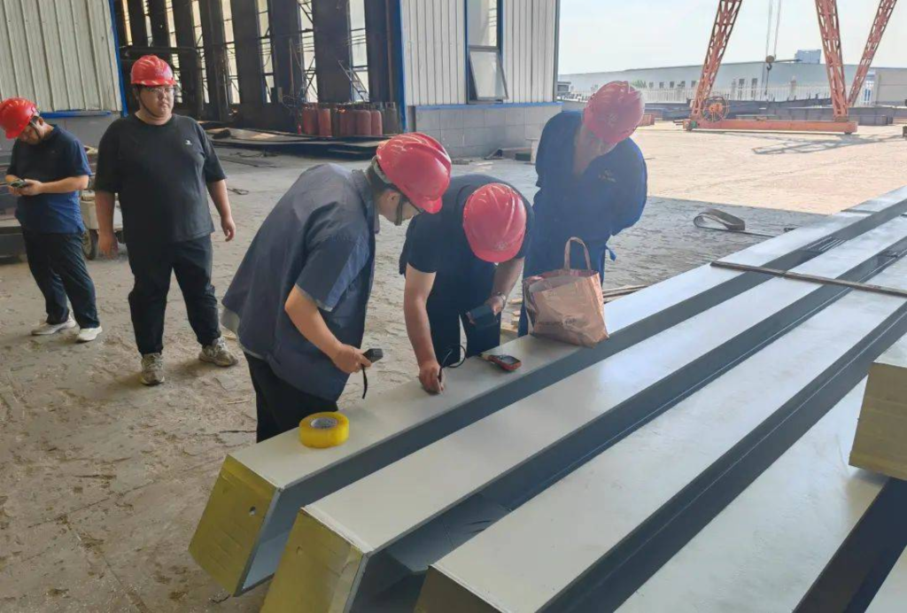
Final Quality Control (FQC) performs a comprehensive audit, inspecting paint aesthetics (zero runs, pinholes, sagging), critical geometry, bolt hole pitches, and component mark traceability. A complete Manufacturing Data Report (MDR) comprising MTRs, NDT records, coating inspection logs, and Certificates of Conformance is compiled to support CE Marking (DoP under EN 1090) and AISC final acceptance.

STANDARDEN 1090 / AISC
METRIC VALUEFull MDR Package
Stage.11

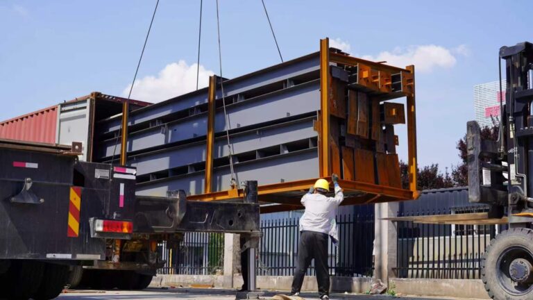
Export Packaging & Logistics Protection

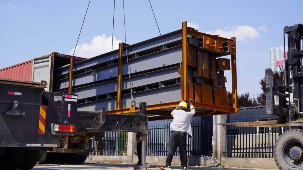
Protective packaging is engineered for containerized (40HQ/OT/FR) and breakbulk ocean freight under heavy maritime transit conditions. Structural members are bundled on heavy-duty steel skids with high-tensile steel strapping. Machined connections are wrapped with VCI anti-corrosion film, EPE foam padding, and heavy rubber cushions. All timber packing complies fully with ISPM 15 phytosanitary standards and IMO Cargo Stowage and Securing (CSS) rules.

STANDARDISPM 15 / IMO CSS
METRIC VALUE40HQ / OT / FR
Stage.12

Global Field Erection & Site Management

We deliver international site erection supervision and turnkey EPCM construction services adhering to OSHA 1926 safety protocols, AISC COSP, and EN 1090-2 erection standards. Field teams, led by multilingual HSE and QA/QC engineers, utilize high-precision total stations to maintain structural plumbness within H/1000 (25mm max). High-Strength Structural Bolting is executed via calibrated Wrench or Turn-of-Nut methods with 100% torque audit documentation.

STANDARDOSHA 1926 / EN 1090-2
METRIC VALUE≤ H/1000

Frequently Asked Questions

What is the estimated cost per square meter for a standard portal frame workshop?

The cost is not fixed; it heavily depends on your local maximum wind speed, snow load, and whether overhead cranes are equipped. Generally, the FOB price for the complete main and secondary steel framing ranges from $55 – $95 / sqm. By providing your dimensions and project location, our engineers will issue a precise BOM estimate within 24 hours.

Absolutely. Our structural engineering team is proficient in mainstream international codes. We will provide complete English structural calculation reports with detailed load combinations and 3D models. Your local Professional Engineer (PE) can directly review, stamp, and submit these documents for government approval.

Without a doubt. For industrial workshops equipped with heavy cranes, we perform specific anti-fatigue dynamic calculations for the H-section main columns and load-bearing corbels. We also add rigid bracing systems in the crane bays, ensuring structural stability even under 24/7 high-frequency operation.

Sufficient. At the beginning of the design, we will request your local 50-year peak wind speed data. By reinforcing secondary framing at roof edges and side walls, and upgrading high-strength bolt connections, the building can be customized to withstand extreme hurricanes up to 250 km/h.

Not at all. Our portal frame system features 100% bolted connections. All cutting, drilling, and full-penetration welding are completed in our automated factory. Your on-site workers only need electric torque wrenches to perform a completely dry assembly like Lego — absolute zero on-site hot work.

We will never let you bear such pointless premiums. For ultra-long main beams exceeding 12 meters, we split them into two or three sections during the design phase. All components are precisely controlled to perfectly fit a 40HC container (internal length 11.8m), eliminating the need for expensive Open Top (OT) containers or bulk/break-bulk vessels.

For such highly corrosive climates, we mandate an upgraded anti-corrosion system. The main steel frame undergoes Sa2.5 industrial shot blasting before leaving the factory to completely strip mill scale, followed by multi-layer heavy-duty epoxy zinc-rich paint (or full hot-dip galvanization). Secondary purlins will use high-strength galvanized coils with a zinc coat up to Z275.

The standard cycle is typically 40 to 50 days. The timeline breakdown is as follows: within 1-2 weeks after signing the contract, we will output 3D models and shop drawings for your review and approval. Once drawings are frozen, raw material procurement, fully automated CNC fabrication, welding, and coating usually take 4-5 weeks to complete and load into containers.

REQUEST A QUOTE

Send Us Your Drawings or BOQ

Tell us the footprint, span, crane capacity and local loads — our engineering team reviews every request and replies with a preliminary assessment.

🔒 100% Private and Secure, No Spam