
Related Projects
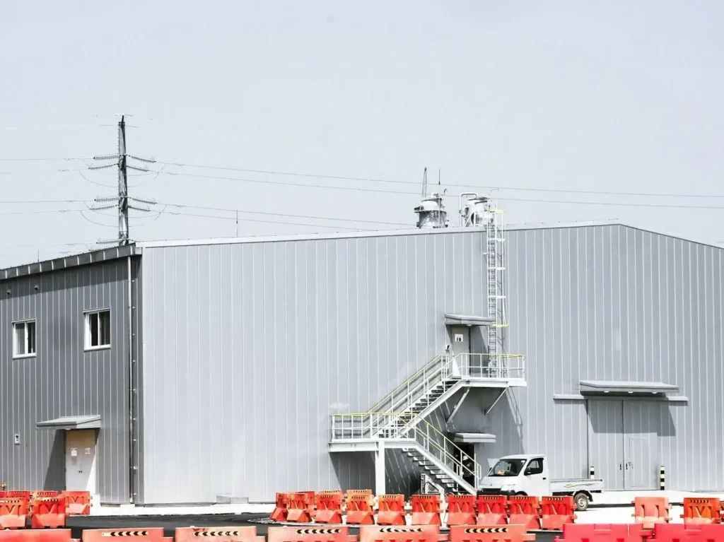
Steel structures we fabricated and shipped for the same kind of building.

SynJect ENGINEERING
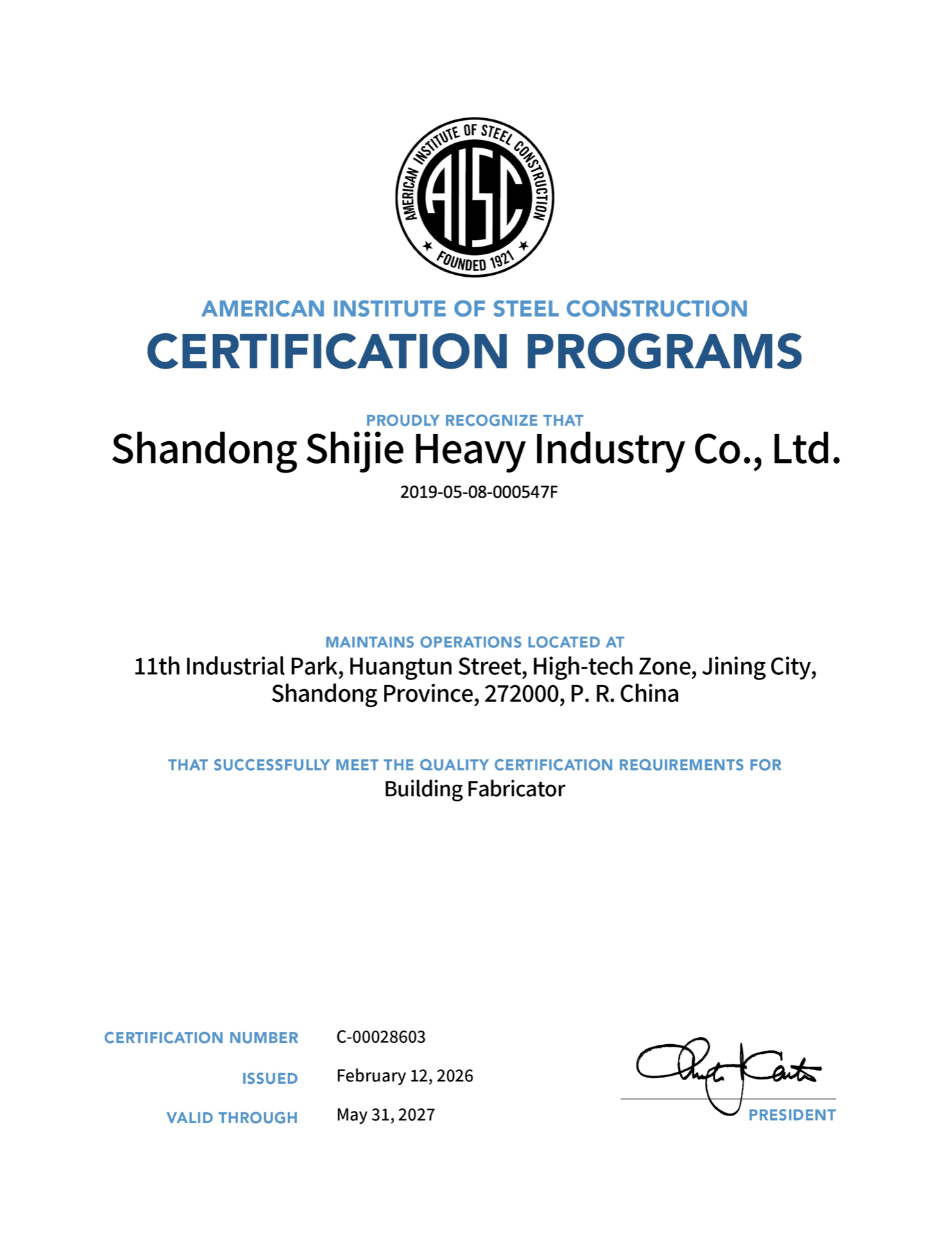
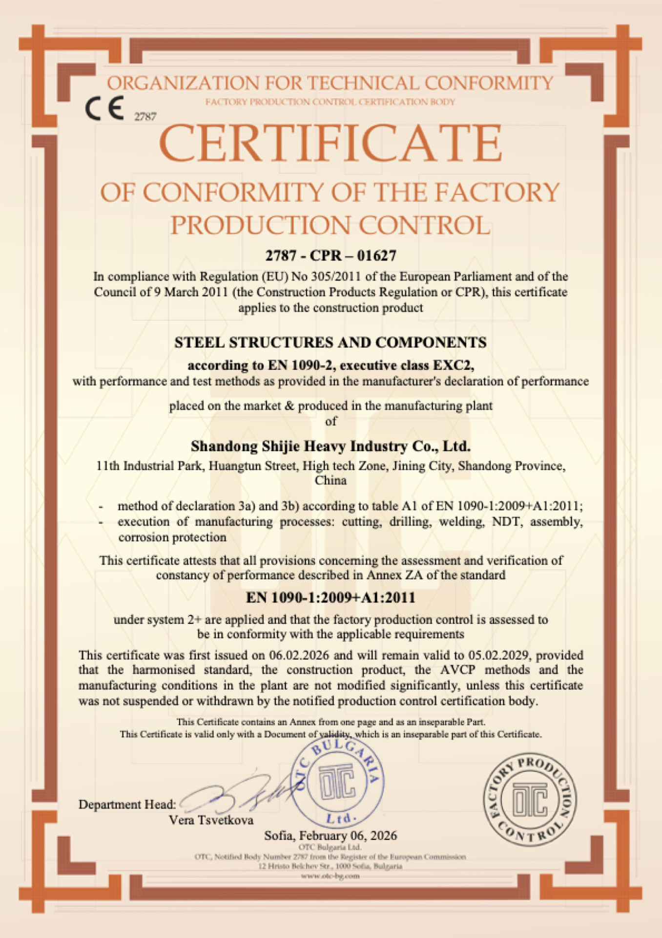
From Microns to Megastructures — 12 Rigorous Stages Certified to AISC & EN 1090


Detailed Engineering & Shop Drawing Development
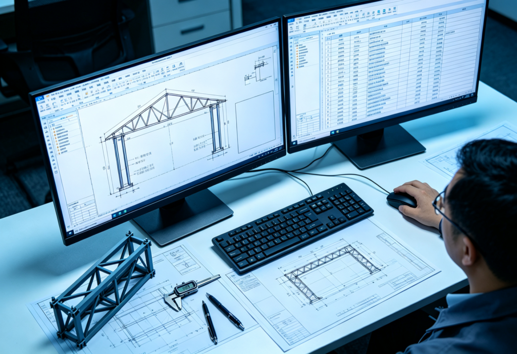
Utilizing advanced BIM platforms such as Tekla Structures, detailed 3D modeling and shop drawings are executed strictly in compliance with AISC 360 or Eurocode 3 (EN 1993). Connection designs are rigorously verified, with manufacturing drawings generated to ISO 2768-m tolerance standards. 100% clash detection with primary architectural and MEP systems is performed to ensure zero structural conflicts during field erection.
Nesting & Material Optimization
Intelligent nesting layouts are performed using advanced software like FastCAM/SigmaNEST in accordance with EN 10029 / ASTM A6 dimensional standards. Accounting for cutting kerf (2mm-5mm depending on plate thickness) and thermal contraction allowances, raw material utilization exceeds 92%. Offcuts are digitally barcode-tracked to ensure 100% mill test report (MTR) traceability.
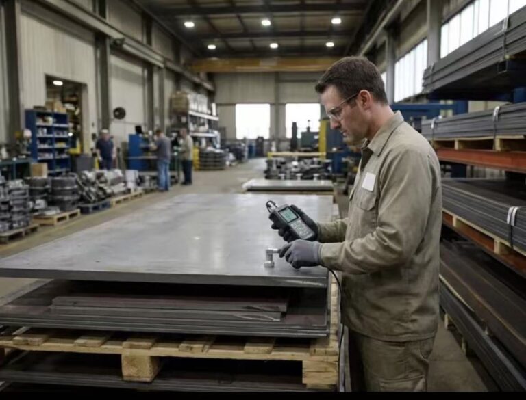
Raw Material Incoming Inspection
All structural steel (Q355B/C/D, ASTM A572 Gr.50, S355JR/J2) must be accompanied by EN 10204 3.1 Mill Test Reports (MTR). Incoming quality control conducts 100% dimensional and visual inspections under ASTM A6 / EN 10029, verifying thickness tolerances (Class A/B) and internal lamination integrity via Ultrasonic Testing (UT) to ASTM A435. Chemical composition and mechanical properties are spot-verified by accredited 3rd-party labs.
CNC Cutting & Edge Preparation
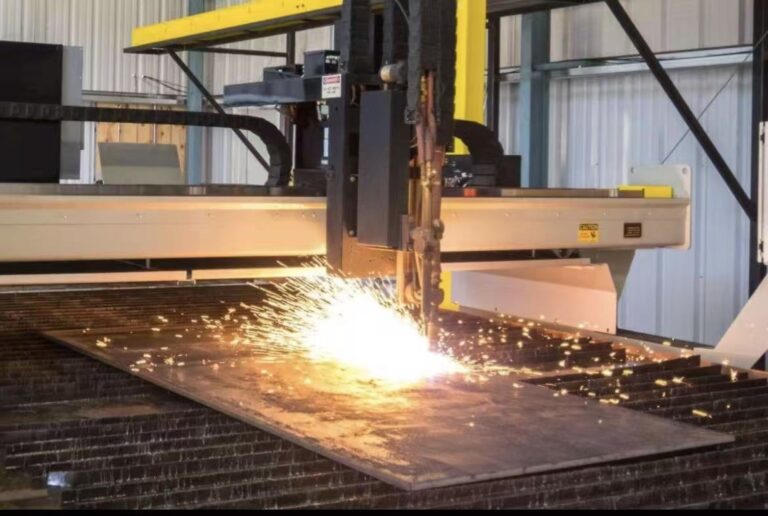
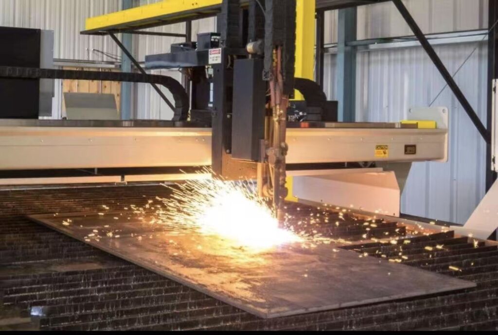
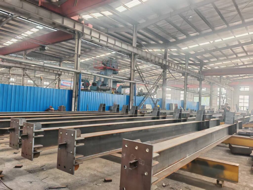
Plate profiling and component cutting are executed via CNC oxy-fuel, high-definition plasma, and multi-kW fiber laser equipment. Cut surface quality strictly complies with EN ISO 9013 for perpendicularity and surface roughness (Range 3/4 tolerance). Multi-axis CNC beveling machines execute weld prep bevel angles within ±2.5° and root face dimensions within ±1.0 mm.
Primary Structural Welding
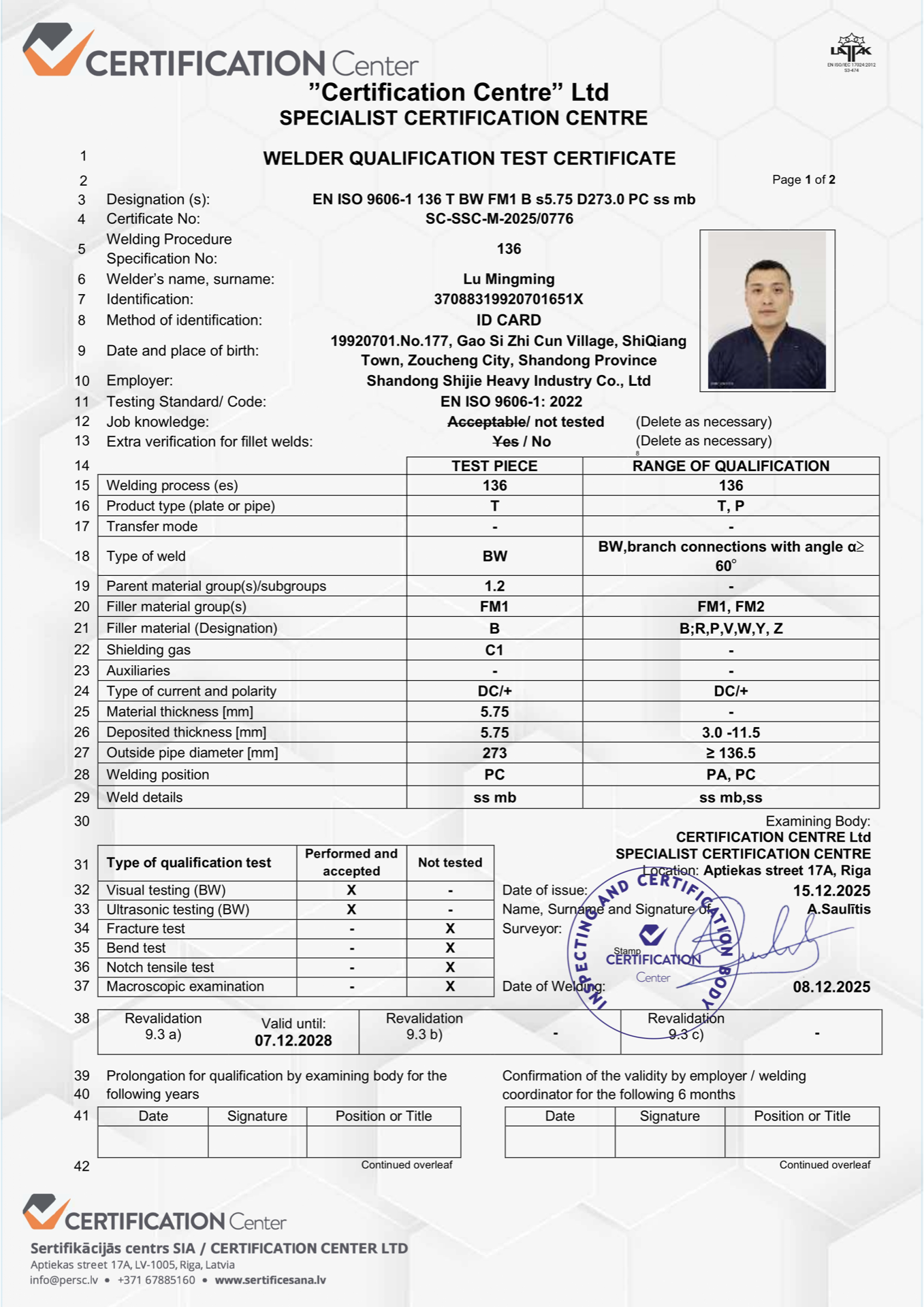
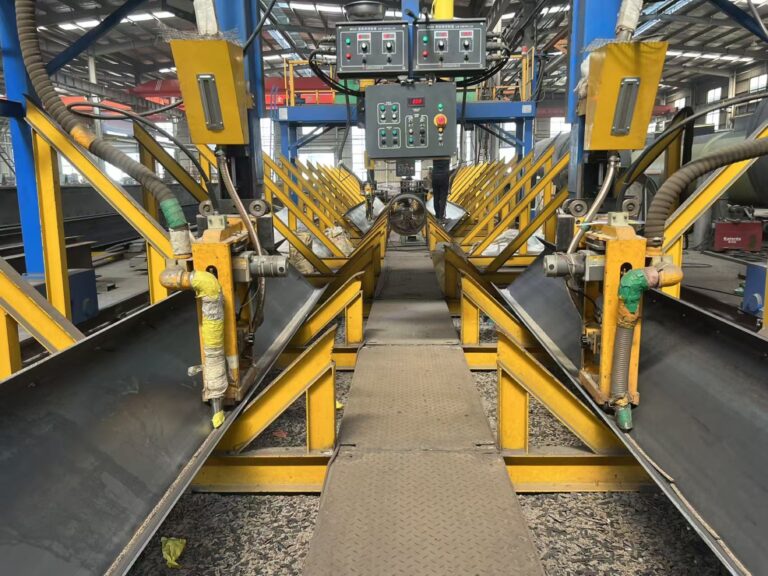
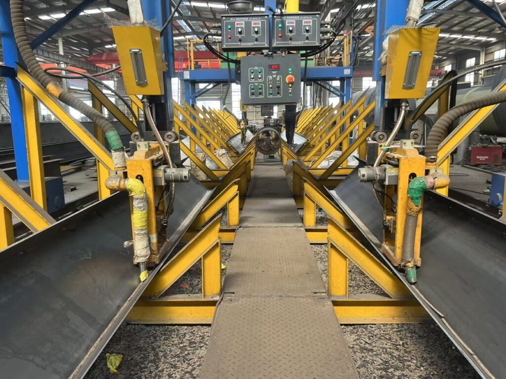
Welding is performed exclusively by AWS D1.1 or EN ISO 9606 certified welders using qualified Welding Procedure Specifications (WPS) supported by Procedure Qualification Records (PQR) per AWS D1.1 / ISO 15614. Submerged Arc Welding (SAW) and Flux-Cored Arc Welding (FCAW) dominate Complete Joint Penetration (CJP) and fillet welds. Heat input is strictly controlled, achieving weld quality levels conforming to ISO 5817 Quality Level B or AWS D1.1 standards.
Weld Distortion Straightening
Post-weld angular distortion, camber, and sweep are rectified using automated hydraulic flange straighteners and controlled thermal flame straightening. Heating temperatures for High-Strength Low-Alloy (HSLA) steels are strictly maintained between 600-650 Celsius (air-cooled, zero water quenching) to prevent microstructural degradation. Post-straightening straightness tolerances meet ±3 mm, conforming to EN 1090-2 Execution Class 2 (EXC2) and AISC COSP standards.
Non-Destructive Testing (NDT)
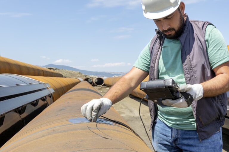
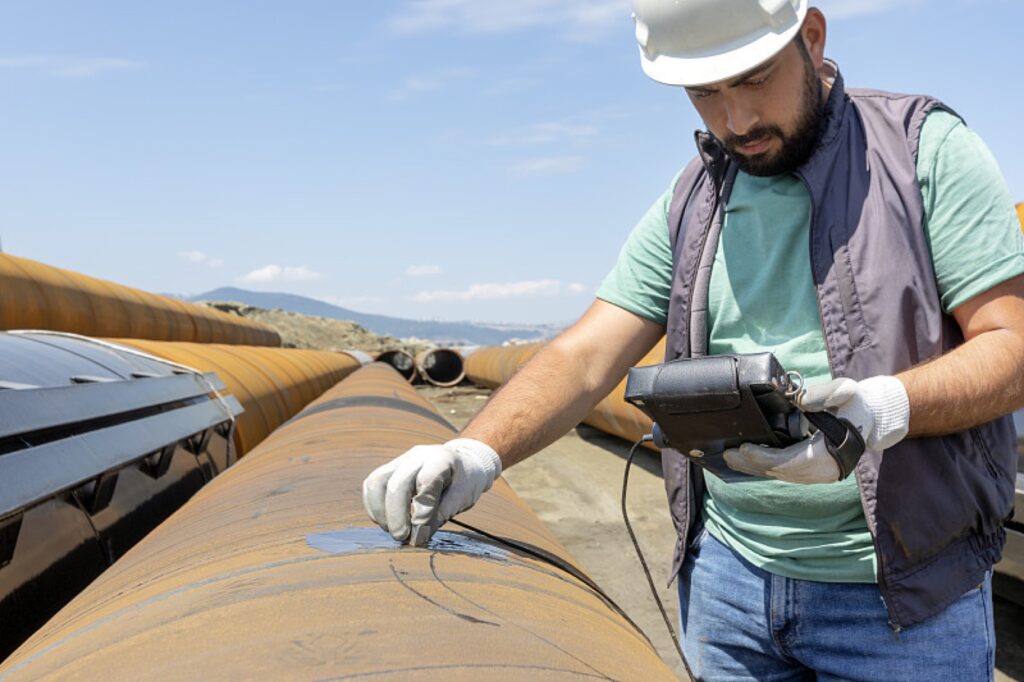
NDT protocols are operated by ISO 9712 / ASNT Level II certified NDT personnel. 100% of critical Complete Joint Penetration (CJP) welds undergo Ultrasonic Testing (UT per ISO 17640 / ASTM E164) or Magnetic Particle Testing (MT per ISO 17638 / ASTM E709). Radiographic Testing (RT) is applied as requested for heavy sections. Weld acceptance conforms strictly to ISO 11666 Acceptance Level 1 or AWS D1.1 criteria.
Trial Assembly & Shop Alignment
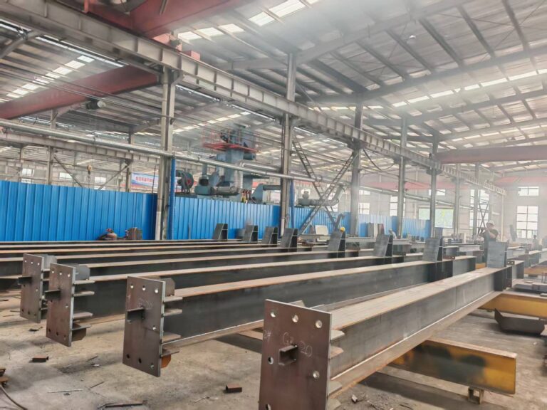
Complex geometries, long-span trusses, and heavy framing undergo 1:1 physical trial assembly or high-precision 3D laser scanning virtual assembly per EN 1090-2 / AISC requirements. Bolt hole alignment is verified (≥95% free-pass rate for high-strength bolts), and critical dimensions (span, camber, 3D spatial alignment) are verified within tight tolerance limits (±2.0 mm) to eliminate site fitting risks.
Surface Preparation & Protective Coating
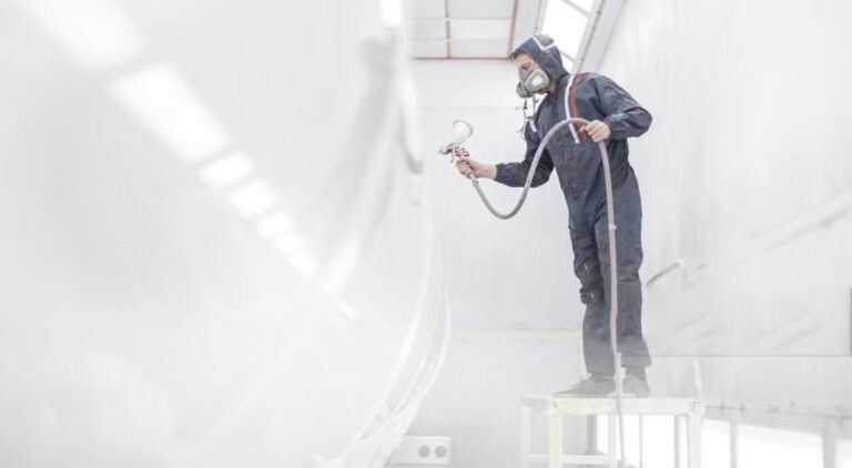
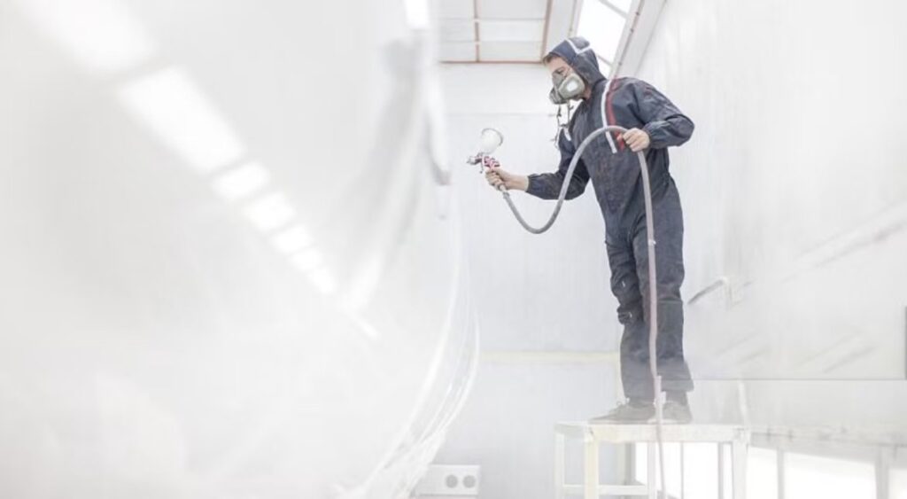
Structural members undergo automated shot blasting to achieve SSPC-SP10 / NACE No. 2 / ISO 8501-1 Sa 2.5 cleanliness, with a surface profile (anchor depth) of 45-75 microns. High-performance protective coatings are applied using airless spray technology in compliance with ISO 12944 (C3 to CX corrosive environments), featuring Zinc-Rich Epoxy Primers, Epoxy Micaceous Iron Oxide Intermediate coats, and Polyurethane/Fluorocarbon Topcoats. Dry Film Thickness (DFT) is verified adhering strictly to the 90/10 rule.
Final Quality Inspection & Certification
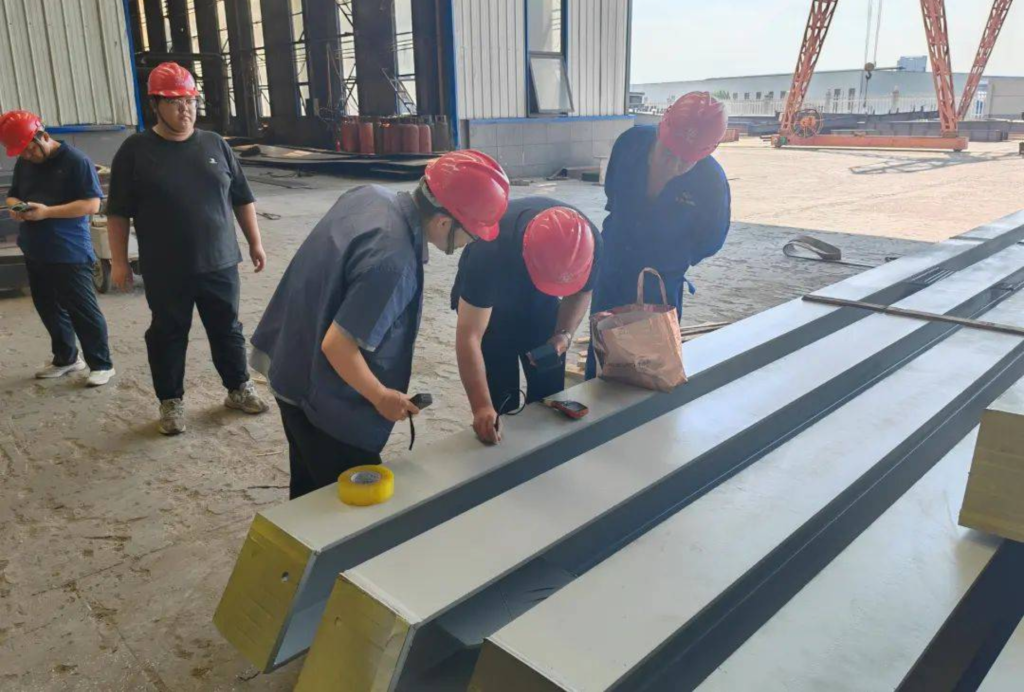
Final Quality Control (FQC) performs a comprehensive audit, inspecting paint aesthetics (zero runs, pinholes, sagging), critical geometry, bolt hole pitches, and component mark traceability. A complete Manufacturing Data Report (MDR) comprising MTRs, NDT records, coating inspection logs, and Certificates of Conformance is compiled to support CE Marking (DoP under EN 1090) and AISC final acceptance.
Export Packaging & Logistics Protection
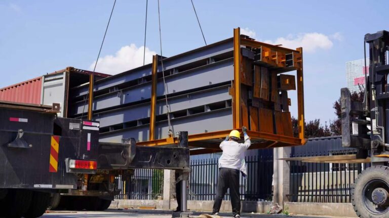
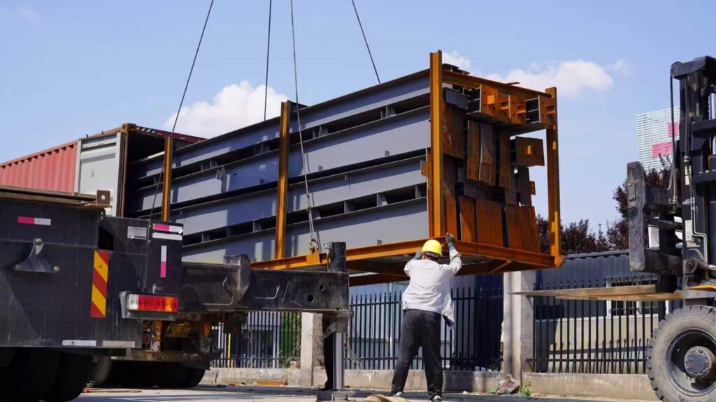
Protective packaging is engineered for containerized (40HQ/OT/FR) and breakbulk ocean freight under heavy maritime transit conditions. Structural members are bundled on heavy-duty steel skids with high-tensile steel strapping. Machined connections are wrapped with VCI anti-corrosion film, EPE foam padding, and heavy rubber cushions. All timber packing complies fully with ISPM 15 phytosanitary standards and IMO Cargo Stowage and Securing (CSS) rules.
Global Field Erection & Site Management
We deliver international site erection supervision and turnkey EPCM construction services adhering to OSHA 1926 safety protocols, AISC COSP, and EN 1090-2 erection standards. Field teams, led by multilingual HSE and QA/QC engineers, utilize high-precision total stations to maintain structural plumbness within H/1000 (25mm max). High-Strength Structural Bolting is executed via calibrated Wrench or Turn-of-Nut methods with 100% torque audit documentation.