

Pre-Engineered Buildings

Anchor Bolts

Cast-in anchor bolts for portal frame column bases, supplied with the plates, nuts, washers and setting templates so the foundation contractor casts them to the steel geometry. Shipped as an early consignment because bolt position error at the foundation is the single most expensive thing to correct on a steel erection site.

Anchor bolts are the first steel on site and the last thing anyone wants to move. We supply them with the anchor plates, nuts and washers, the setting-out template for each column base and a layout drawing referenced to your grid with tolerance notes.

Because foundations are poured weeks before the frame arrives, anchor bolts ship as a separate early consignment. Quantities are counted from the shop drawings plus spares, so a damaged or lost bolt does not stop a pour.

Part of Connection & Fasteners in PEB Systems (Pre-Engineered Buildings) . Other components in this sub-system: Tie Rods · Sleeves (32mm / 1-1.5m)

Technical Specifications

ItemSpecification
Design basisGrade, geometry, embedment length and diameter per the base design your engineer issues
MaterialBolt grade and plate material to the design, with certificates
TemplatesSetting template per column base plus layout drawing referenced to the grid
Corrosion protectionGalvanised or coated exposed length as specified
QuantitiesCounted from the shop drawings plus spares
DocumentationMaterial certificates, setting-out drawing and template schedule with the consignment

Section sizes, grades and quantities for this product are issued with the quotation once your design basis and loads are received.

Advantages vs Engineering Considerations

AdvantagesEngineering Considerations
Template with every baseSetting templates hold the bolt group at the right position and level while the concrete is poured.Best suited to single-storey and low-rise buildings; multi-storey floors or heavy mezzanines call for a braced or moment frame instead.
Layout on your gridThe setting-out drawing is referenced to your grid with tolerance notes, so surveyors work from one document.Column-free spans increase rafter depth and foundation reactions; very long spans may be more economical as trusses or space frames.
Early consignmentAnchor bolts and embedded parts ship first, by air or with the first container, so foundations are not waiting for the steel.Frames are sized to the stated crane duty and loads; a later change of crane class or roof equipment needs a design check.
Matched hardwareNuts, washers and plates are supplied as a matched set with material certificates.Cold-formed purlins and girts reach their design capacity only with correct cladding fixing and bracing.
CERTIFICATIONS & COMPLIANCE

Certifications & Compliance

Every shipment leaves with the documents an auditor asks for. Scroll the row and open any certificate at full size.

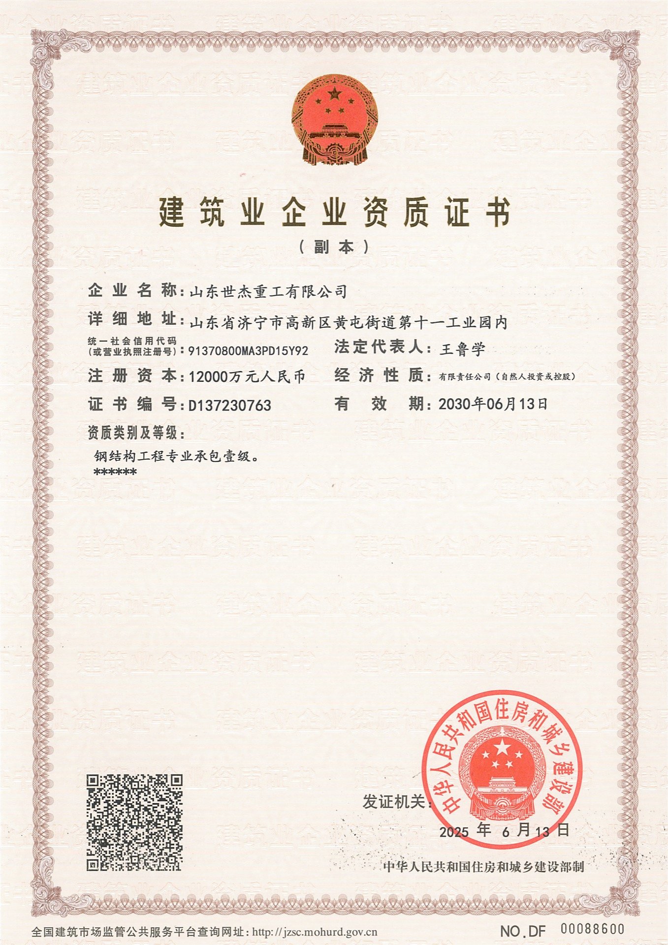
China Steel Structure Manufacturing Grade I

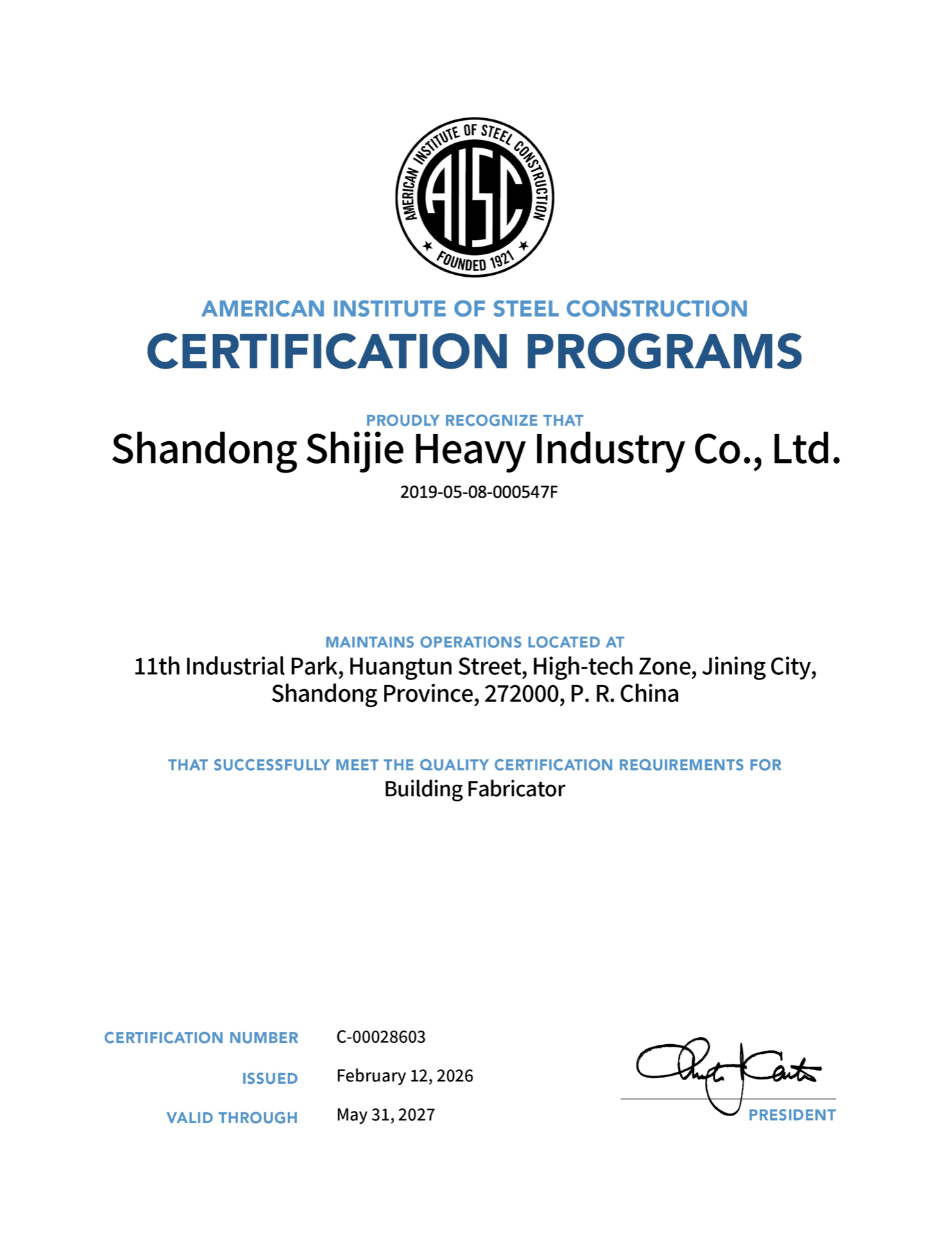
AISC Certification

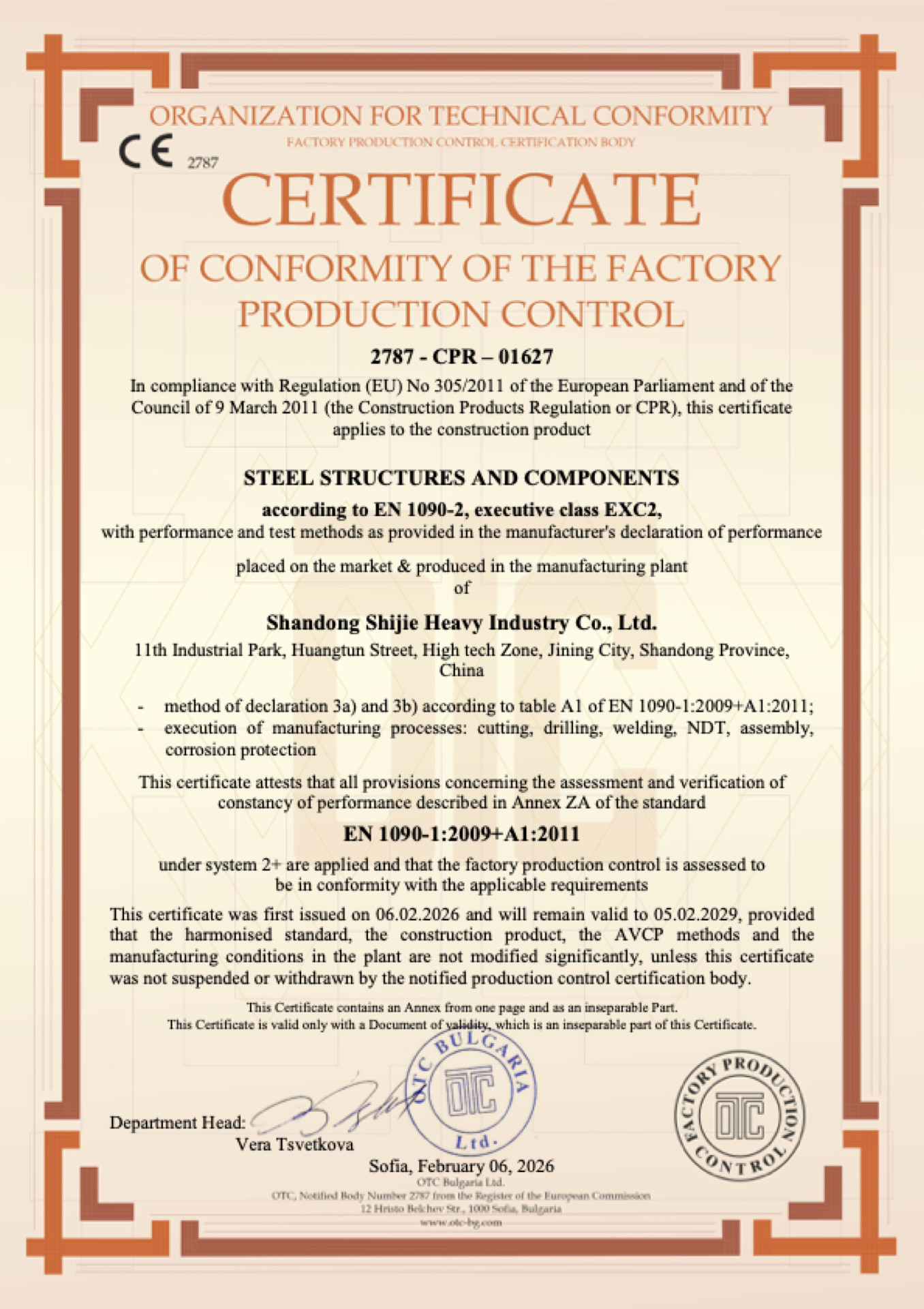
CE Marking – EN 1090-2 (CPR 01627)

OTC Document of Validity

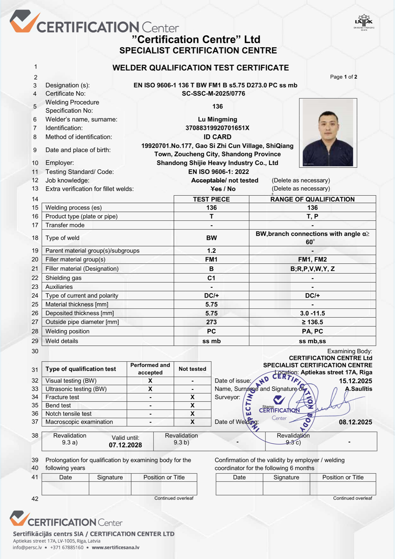
International Welder Certification

Enterprise Qualifications Portfolio

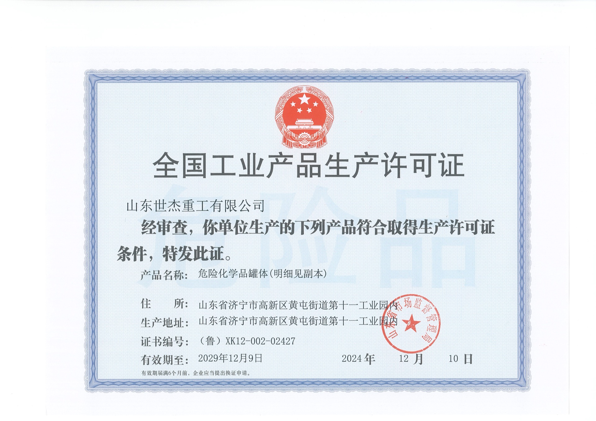
DG Packaging Certificate

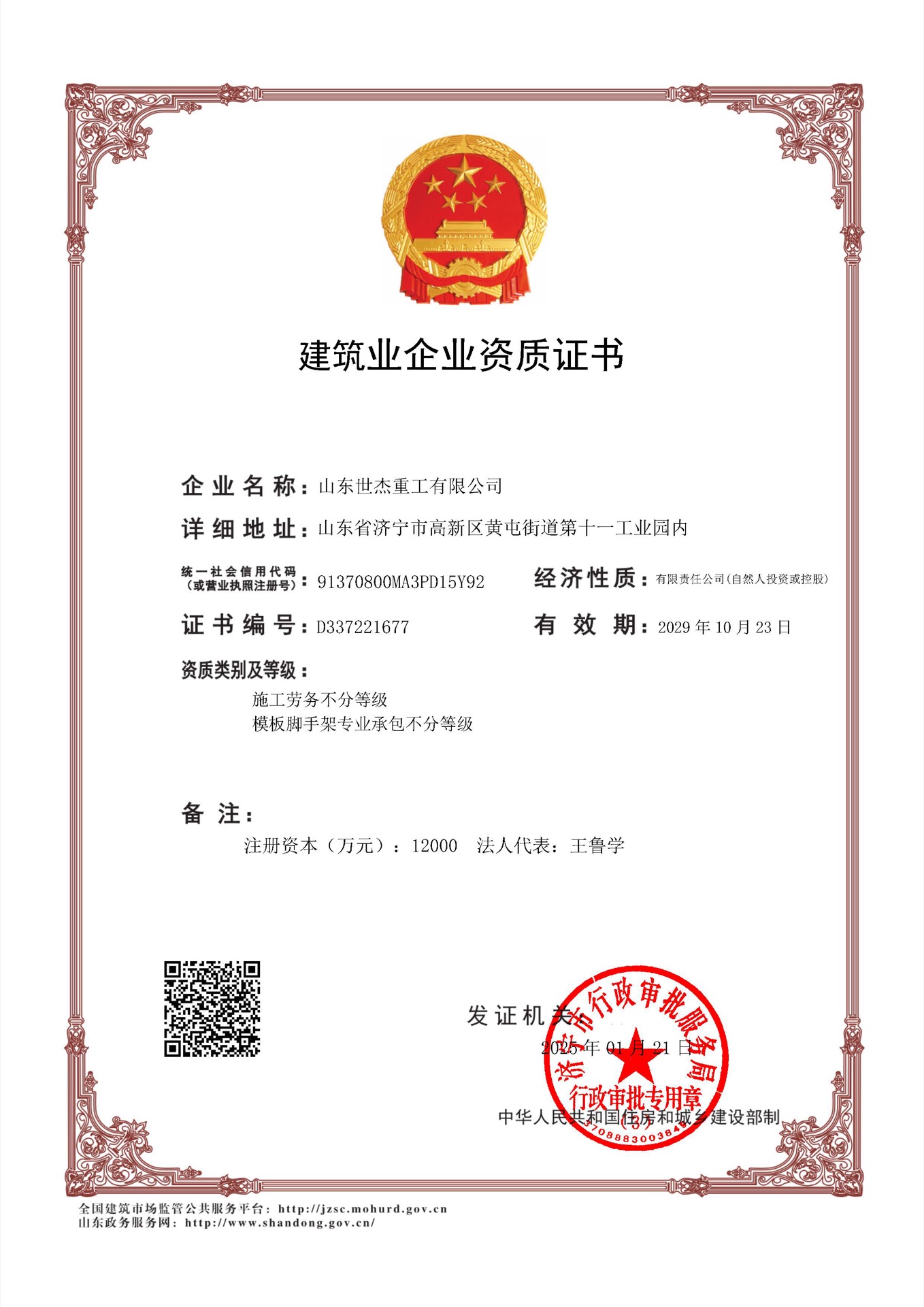
Labor & Scaffolding Contracting

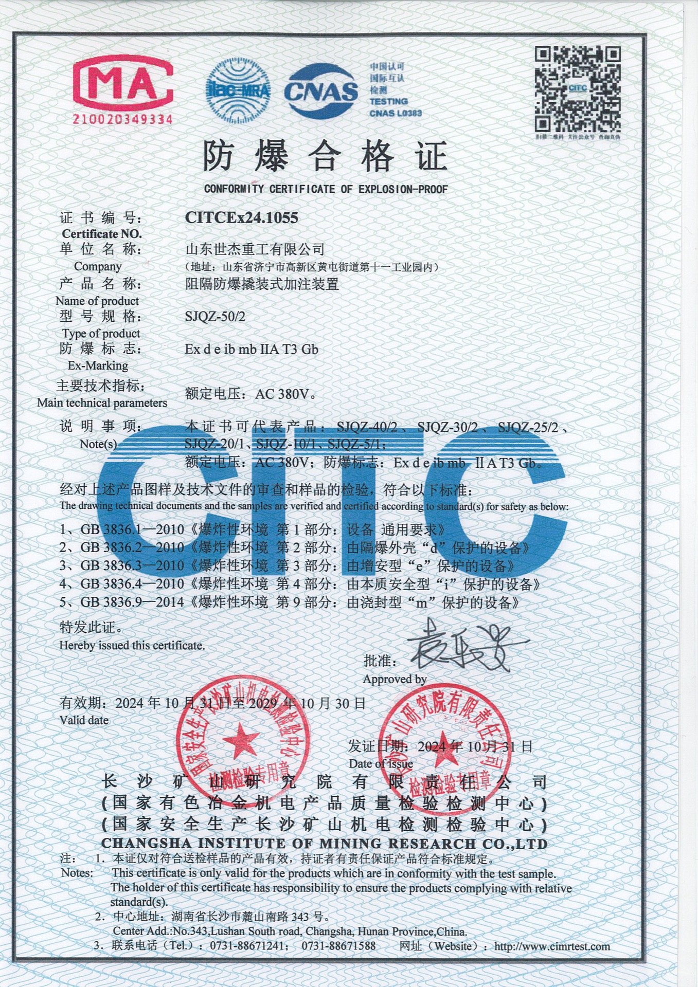
Explosion-Proof Certificate

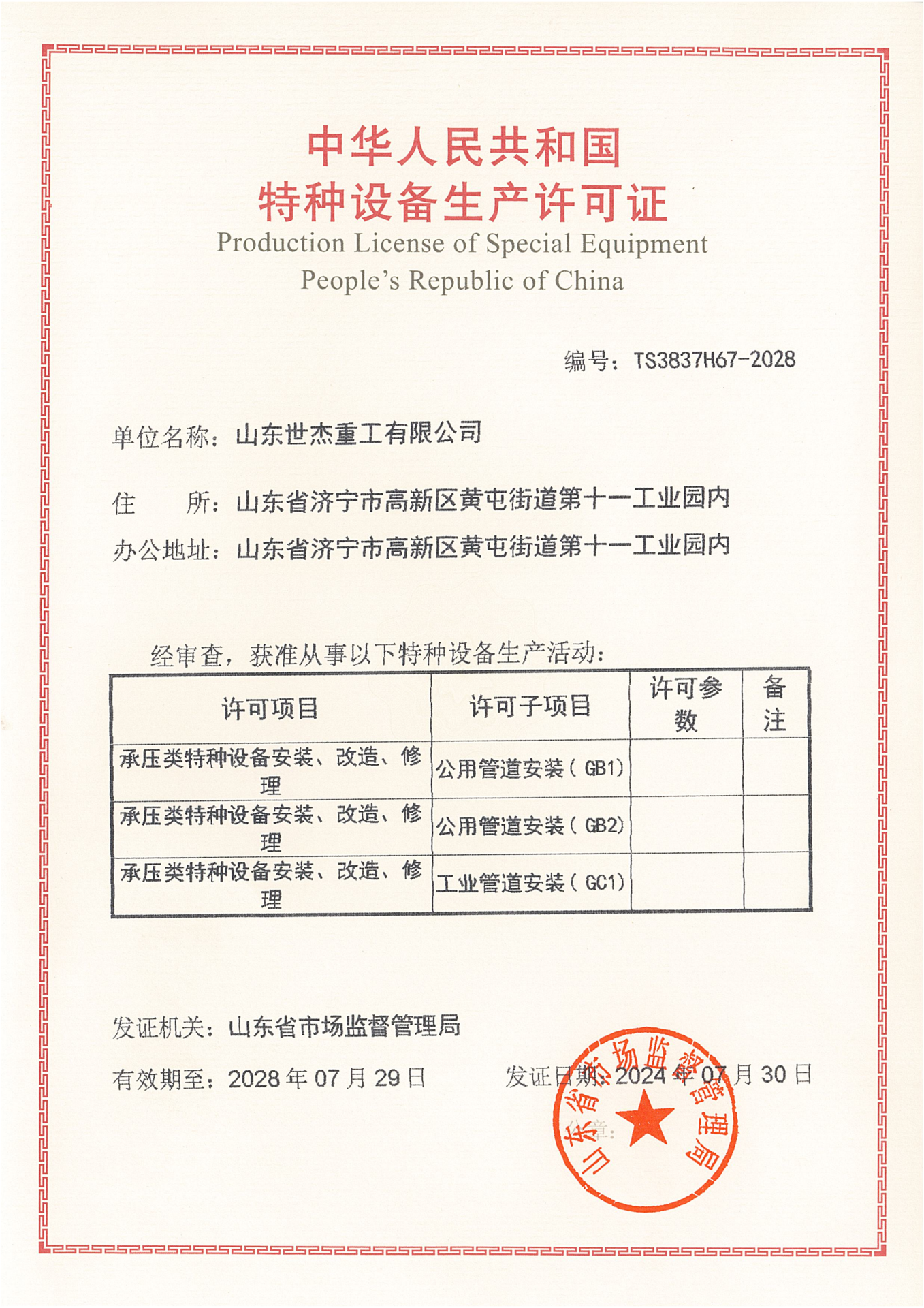
Industrial Pipeline Installation GC1

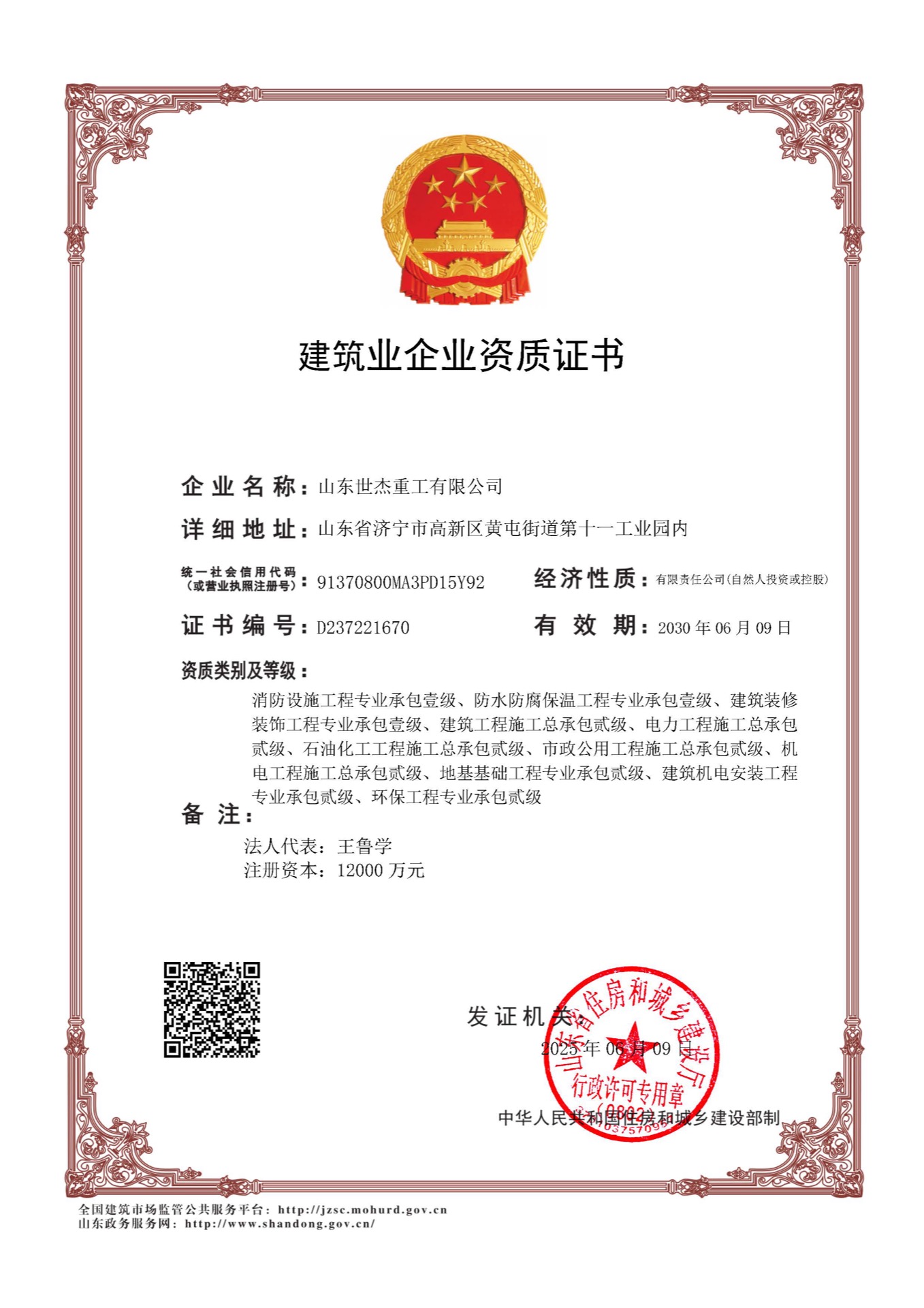
Power Facility License

Have drawings or a BOQ ready? Send them through the form and our engineers reply with a preliminary assessment.

SynJect

SynJect. Scale. Precision. Certainty.

SYNJECT delivers comprehensive steel structure solutions engineered for the global value chain. From investors seeking ROI to engineers demanding exact compliance, we transform complex blueprints into robust realities—on time and without friction.

SynJect ENGINEERING

From Microns to Megastructures — 12 Rigorous Stages Certified to AISC & EN 1090
Detailed Engineering & Shop Drawing DevelopmentNesting & Material OptimizationRaw Material Incoming InspectionCNC Cutting & Edge PreparationPrimary Structural WeldingWeld Distortion StraighteningNon-Destructive Testing (NDT)Trial Assembly & Shop AlignmentSurface Preparation & Protective CoatingFinal Quality Inspection & CertificationExport Packaging & Logistics ProtectionGlobal Field Erection & Site Management
Stage.01

Detailed Engineering & Shop Drawing Development

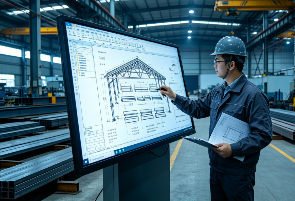
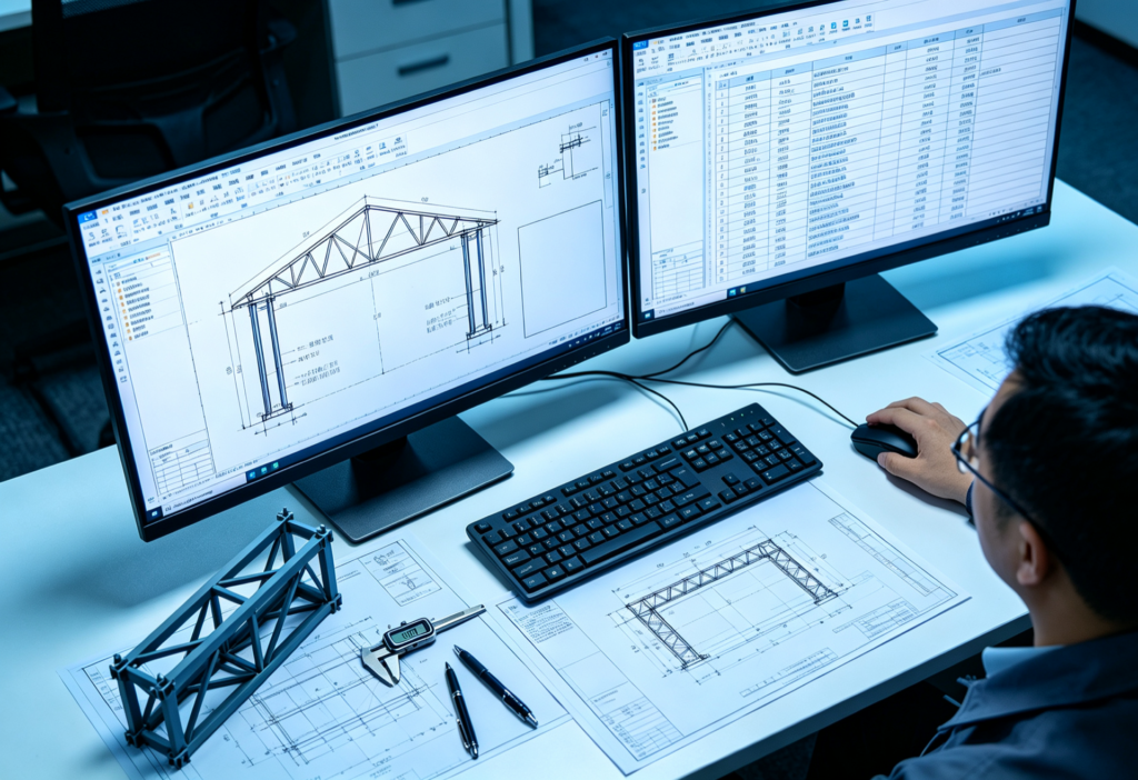
Utilizing advanced BIM platforms such as Tekla Structures, detailed 3D modeling and shop drawings are executed strictly in compliance with AISC 360 or Eurocode 3 (EN 1993). Connection designs are rigorously verified, with manufacturing drawings generated to ISO 2768-m tolerance standards. 100% clash detection with primary architectural and MEP systems is performed to ensure zero structural conflicts during field erection.

STANDARDAISC 360 / EN 1993
METRIC VALUETolerance ISO 2768-m
Stage.02

Nesting & Material Optimization

Intelligent nesting layouts are performed using advanced software like FastCAM/SigmaNEST in accordance with EN 10029 / ASTM A6 dimensional standards. Accounting for cutting kerf (2mm-5mm depending on plate thickness) and thermal contraction allowances, raw material utilization exceeds 92%. Offcuts are digitally barcode-tracked to ensure 100% mill test report (MTR) traceability.

STANDARDEN 10029 / ASTM A6
METRIC VALUEUtilization ≥92%
Stage.03

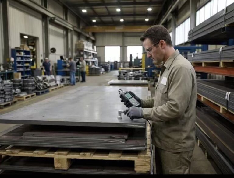
Raw Material Incoming Inspection

All structural steel (Q355B/C/D, ASTM A572 Gr.50, S355JR/J2) must be accompanied by EN 10204 3.1 Mill Test Reports (MTR). Incoming quality control conducts 100% dimensional and visual inspections under ASTM A6 / EN 10029, verifying thickness tolerances (Class A/B) and internal lamination integrity via Ultrasonic Testing (UT) to ASTM A435. Chemical composition and mechanical properties are spot-verified by accredited 3rd-party labs.

STANDARDEN 10204 3.1 / ASTM A435
METRIC VALUE100% MTR + UT
Stage.04

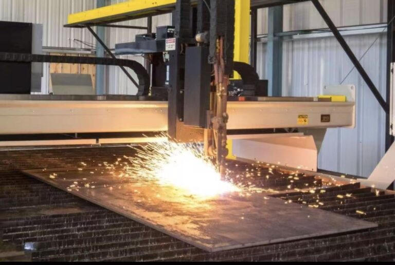
CNC Cutting & Edge Preparation

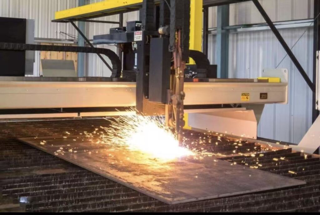
Plate profiling and component cutting are executed via CNC oxy-fuel, high-definition plasma, and multi-kW fiber laser equipment. Cut surface quality strictly complies with EN ISO 9013 for perpendicularity and surface roughness (Range 3/4 tolerance). Multi-axis CNC beveling machines execute weld prep bevel angles within ±2.5° and root face dimensions within ±1.0 mm.

STANDARDEN ISO 9013
METRIC VALUERa ≤12.5μm / ±2.5°
Stage.05

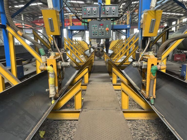
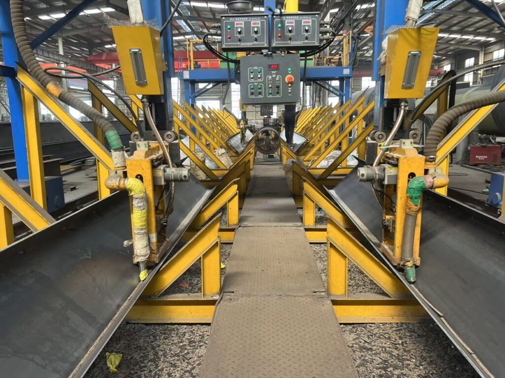
Primary Structural Welding

Welding is performed exclusively by AWS D1.1 or EN ISO 9606 certified welders using qualified Welding Procedure Specifications (WPS) supported by Procedure Qualification Records (PQR) per AWS D1.1 / ISO 15614. Submerged Arc Welding (SAW) and Flux-Cored Arc Welding (FCAW) dominate Complete Joint Penetration (CJP) and fillet welds. Heat input is strictly controlled, achieving weld quality levels conforming to ISO 5817 Quality Level B or AWS D1.1 standards.

STANDARDAWS D1.1 / EN ISO 9606
METRIC VALUEISO 5817 Level B
Stage.06

Weld Distortion Straightening

Post-weld angular distortion, camber, and sweep are rectified using automated hydraulic flange straighteners and controlled thermal flame straightening. Heating temperatures for High-Strength Low-Alloy (HSLA) steels are strictly maintained between 600-650 Celsius (air-cooled, zero water quenching) to prevent microstructural degradation. Post-straightening straightness tolerances meet ±3 mm, conforming to EN 1090-2 Execution Class 2 (EXC2) and AISC COSP standards.

STANDARDEN 1090-2 EXC2 / AISC COSP
METRIC VALUE≤ ±3 mm
Stage.07

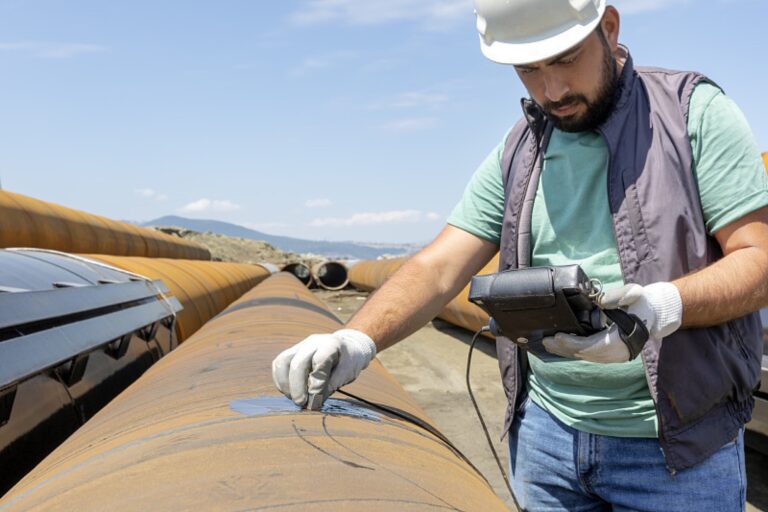
Non-Destructive Testing (NDT)

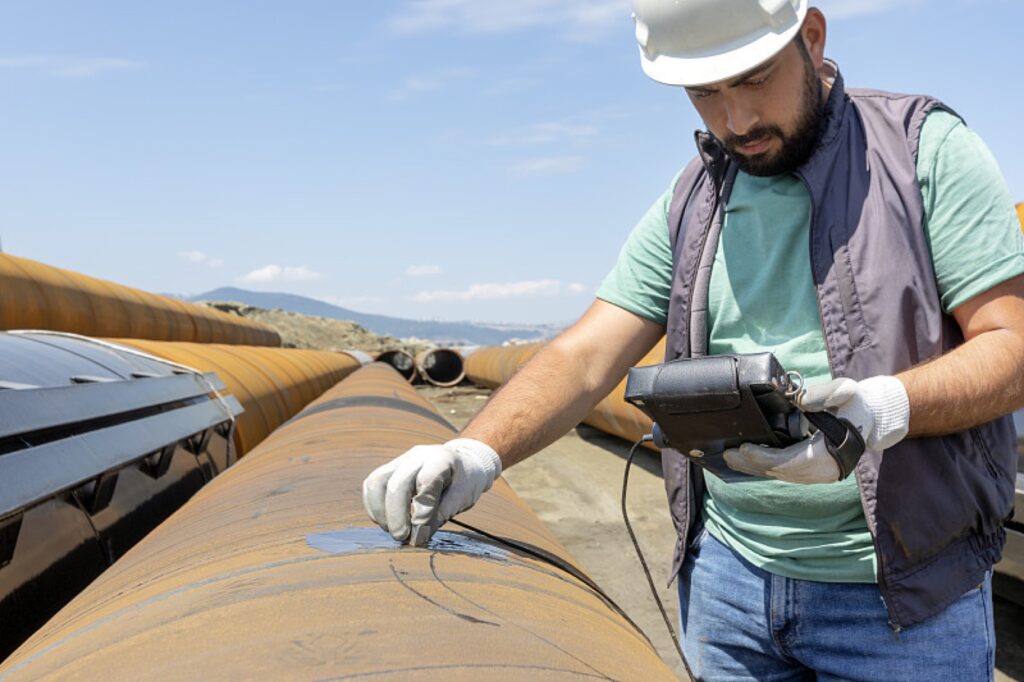
NDT protocols are operated by ISO 9712 / ASNT Level II certified NDT personnel. 100% of critical Complete Joint Penetration (CJP) welds undergo Ultrasonic Testing (UT per ISO 17640 / ASTM E164) or Magnetic Particle Testing (MT per ISO 17638 / ASTM E709). Radiographic Testing (RT) is applied as requested for heavy sections. Weld acceptance conforms strictly to ISO 11666 Acceptance Level 1 or AWS D1.1 criteria.

STANDARDISO 11666 Level 1 / AWS D1.1
METRIC VALUE100% UT on CJP
Stage.08

Trial Assembly & Shop Alignment

Complex geometries, long-span trusses, and heavy framing undergo 1:1 physical trial assembly or high-precision 3D laser scanning virtual assembly per EN 1090-2 / AISC requirements. Bolt hole alignment is verified (≥95% free-pass rate for high-strength bolts), and critical dimensions (span, camber, 3D spatial alignment) are verified within tight tolerance limits (±2.0 mm) to eliminate site fitting risks.

STANDARDAISC / EN 1090-2
METRIC VALUE±2.0 mm / ≥95% pass
Stage.09

Surface Preparation & Protective Coating

Structural members undergo automated shot blasting to achieve SSPC-SP10 / NACE No. 2 / ISO 8501-1 Sa 2.5 cleanliness, with a surface profile (anchor depth) of 45-75 microns. High-performance protective coatings are applied using airless spray technology in compliance with ISO 12944 (C3 to CX corrosive environments), featuring Zinc-Rich Epoxy Primers, Epoxy Micaceous Iron Oxide Intermediate coats, and Polyurethane/Fluorocarbon Topcoats. Dry Film Thickness (DFT) is verified adhering strictly to the 90/10 rule.

STANDARDISO 8501-1 Sa 2.5 / ISO 12944
METRIC VALUE45-75 μm profile
Stage.10

Final Quality Inspection & Certification

Final Quality Control (FQC) performs a comprehensive audit, inspecting paint aesthetics (zero runs, pinholes, sagging), critical geometry, bolt hole pitches, and component mark traceability. A complete Manufacturing Data Report (MDR) comprising MTRs, NDT records, coating inspection logs, and Certificates of Conformance is compiled to support CE Marking (DoP under EN 1090) and AISC final acceptance.

STANDARDEN 1090 / AISC
METRIC VALUEFull MDR Package
Stage.11

Export Packaging & Logistics Protection

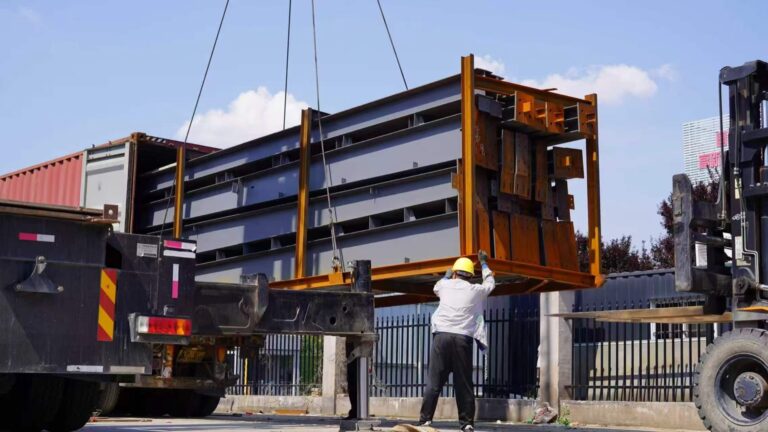
Protective packaging is engineered for containerized (40HQ/OT/FR) and breakbulk ocean freight under heavy maritime transit conditions. Structural members are bundled on heavy-duty steel skids with high-tensile steel strapping. Machined connections are wrapped with VCI anti-corrosion film, EPE foam padding, and heavy rubber cushions. All timber packing complies fully with ISPM 15 phytosanitary standards and IMO Cargo Stowage and Securing (CSS) rules.

STANDARDISPM 15 / IMO CSS
METRIC VALUE40HQ / OT / FR
Stage.12

Global Field Erection & Site Management

We deliver international site erection supervision and turnkey EPCM construction services adhering to OSHA 1926 safety protocols, AISC COSP, and EN 1090-2 erection standards. Field teams, led by multilingual HSE and QA/QC engineers, utilize high-precision total stations to maintain structural plumbness within H/1000 (25mm max). High-Strength Structural Bolting is executed via calibrated Wrench or Turn-of-Nut methods with 100% torque audit documentation.

STANDARDOSHA 1926 / EN 1090-2
METRIC VALUE≤ H/1000

Frequently Asked Questions

Do you supply anchor bolts with the setting-out template?

Yes. Anchor bolts ship with the template and the setting-out drawing, because bolt position error at the foundation is the single most expensive thing to correct on a steel erection site.

Yes. Anchor bolts, embedded plates and templates ship by air or with the first container so foundations are cast before the frame arrives.

Whatever your connection design specifies — typically HSFG assemblies to EN 14399 or ASTM F3125 for slip-critical joints. Nuts and washers are supplied as a matched assembly from the same manufacturer, never mixed.

The setting-out drawing carries the tolerance the base plate holes allow. Outside that, tell us before the frame ships and the base plates are re-drilled or slotted to the surveyed positions rather than corrected in concrete.

Yes. Send the base plate drawings and the foundation design; bolts are sized to the reaction and embedment in that design and shipped with templates.

Yes. We quote sub-systems separately where the scope makes sense — for example secondary framing or bracing against an existing structure. Send the BOQ and connection details of the receiving structure so the interfaces are engineered rather than assumed.

Whichever your design specifies. Design intent to AISC 360 or Eurocode 3 (EN 1993), execution to EN 1090-2 EXC2 under certificate 2787-CPR-01627.

Never without written approval. If a specified section has a long lead time we propose the alternative with the calculation showing equivalence, and you decide.

Mill test certificates per heat, WPS/PQR, welder qualification certificates, NDT reports with technician level, and coating thickness records against the specified ISO 12944 system.

The standard cycle for a single-building scope is 40 to 50 days: 1–2 weeks to shop drawings for your approval, then 4–5 weeks for procurement, fabrication, coating and loading.

REQUEST A QUOTE

Send Us Your Drawings or BOQ

Tell us the footprint, span, crane capacity and local loads — our engineering team reviews every request and replies with a preliminary assessment.

🔒 100% Private and Secure, No Spam